
Print a flyer to display alongside your CycleKart at shows and events that links directly to this build-page

Pinned Items
Recent Activities
-
 Post is under moderationStream item published successfully. Item will now be visible on your stream.
 -
 Post is under moderationStream item published successfully. Item will now be visible on your stream.
 -
Pinky reacted to this post about 7 months agoBonnet louvres
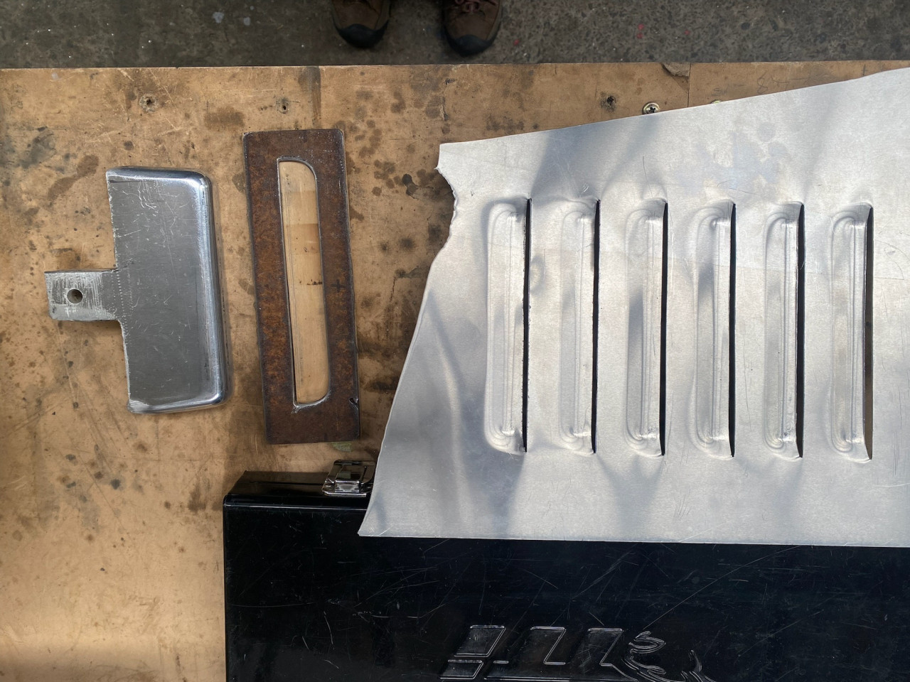
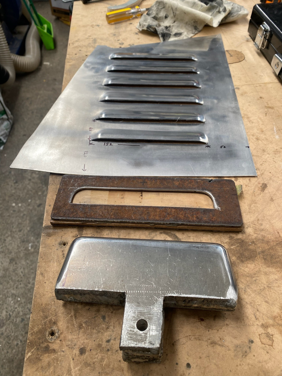
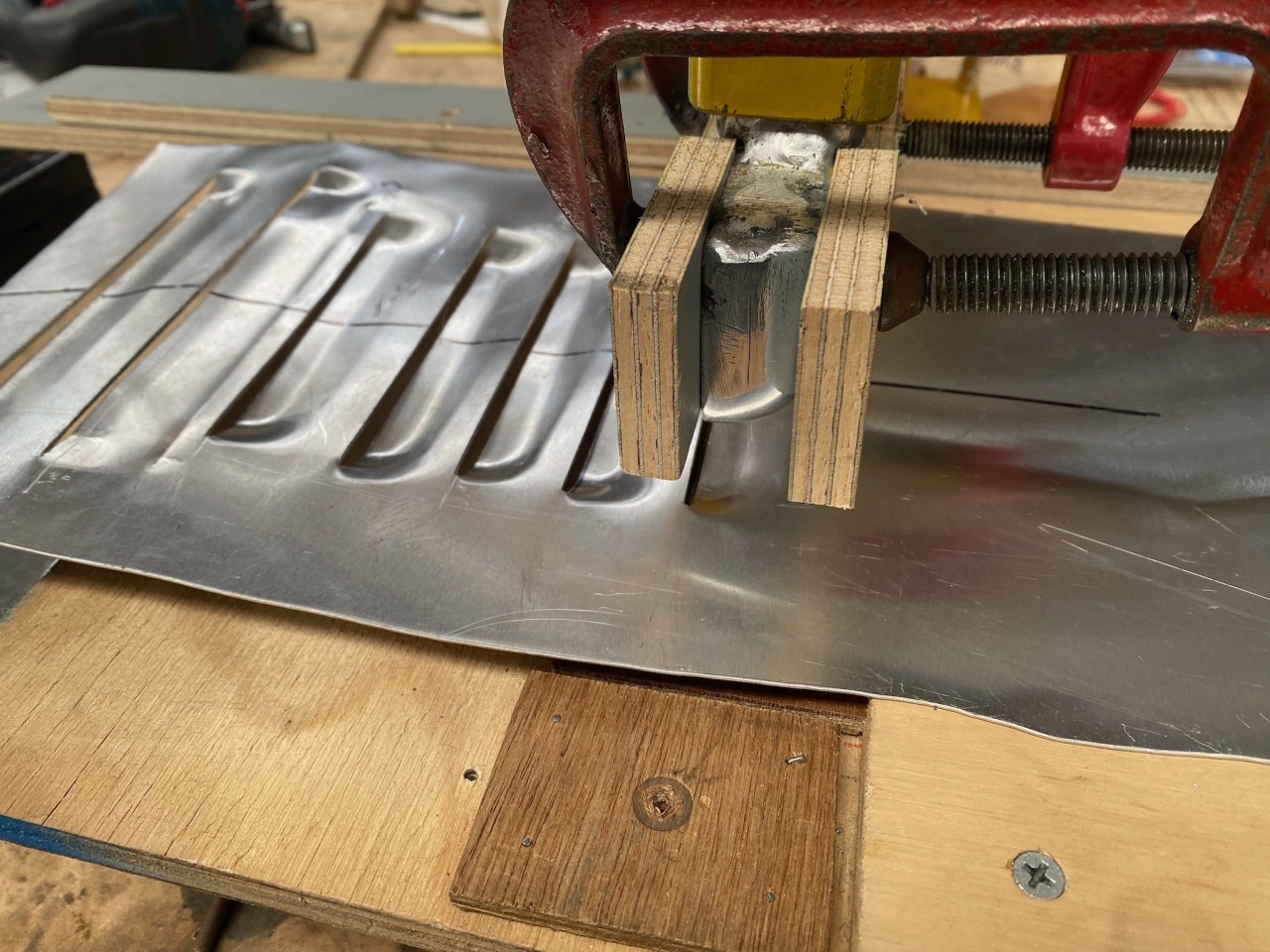
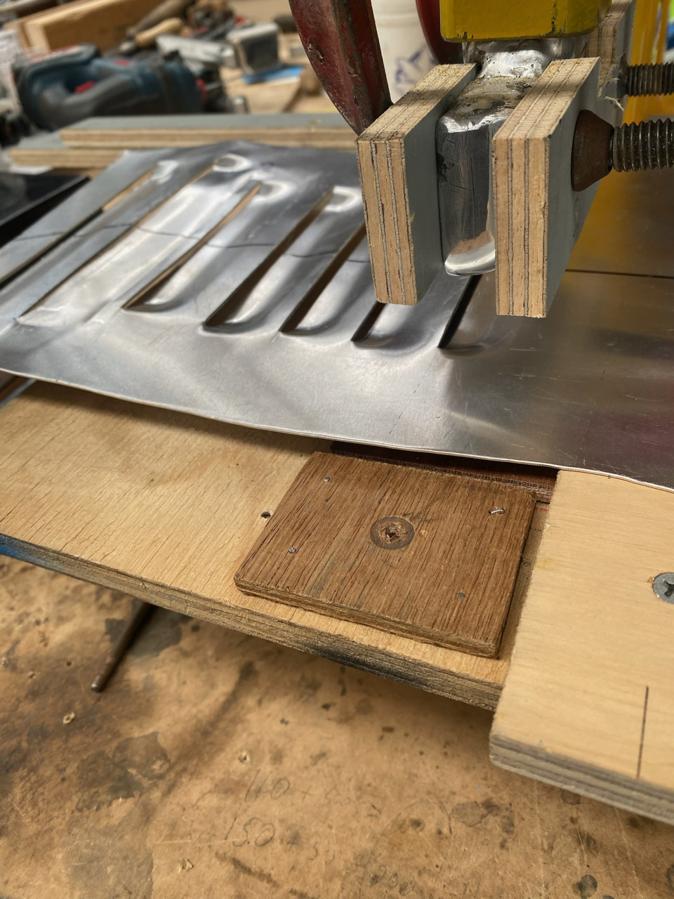
In order to achieve the look of the inspiration car, we needed to work out how to create louvres in the side panels of the bonnet. Some research online suggested a few potential methods. In the end we opted to use a punch and die set in a manual press. The punch is made of aluminium plate which we welded together to get the...Bonnet louvresMore
In order to achieve the look of the inspiration car, we needed to work out how to create louvres in the side panels of the bonnet. Some research online suggested a few potential methods. In the end we opted to use a punch and die set in a manual press. The punch is made of aluminium plate which we welded together to get the required thickness. The punch was shaped by hand to give the inside profile of the louvre. The die is a piece of steel with a long 'D' shaped hole in it. The die ha about 3mm of clearance around the punch (when the end of the punch is about 4mm below the top surface of the die). We rounded the top edge of the die somewhat and polished out and surface roughness so it didn't transfer to the aluminium sheet. To press a louvre we needed to cut the sheet for the opening of the louvre with a thin cut off disk in a grinder. Trail and error showed us that the length of the cut was key to getting the louvre to press cleanly. We also discovered that the radius of the ends of the punch needed to be enlarged as a tight radius resulted in the aluminium tearing. A larger radius on the ends stretches the sheet less. We found that it was useful to fix wooden blocks each side of the punch to hold the sheet flat when the punch was at maximum travel. This helps produce a more defined bend at the edges of the louvres. Once we were happy with the set up, we set a fence that we could run the panel along to ensure all the louvres were a consistent distance from the edge and at the same angle. Once we were set up it didn't take long to press the actual panels. 90% of the work is required to make the first louvre.Post is under moderationStream item published successfully. Item will now be visible on your stream. -
Mick commented on this post about 1 year agoChassis finishing
With the bodywork getting close and having decided there aren't any serious changes required to the running gear, it was time to disassemble the kart so the chassis and floor pan can be finished. Steelwork was finished in black enamel and the wooden floor pan got a coat of tinted varnish. After finishing, the kart is looking...Chassis finishingMore
With the bodywork getting close and having decided there aren't any serious changes required to the running gear, it was time to disassemble the kart so the chassis and floor pan can be finished. Steelwork was finished in black enamel and the wooden floor pan got a coat of tinted varnish. After finishing, the kart is looking nice and clean. Ready for body work.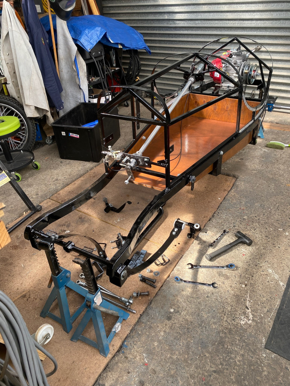 Post is under moderationStream item published successfully. Item will now be visible on your stream.
 -
1930s Amilcar commented on this post about 1 year agoTransportation
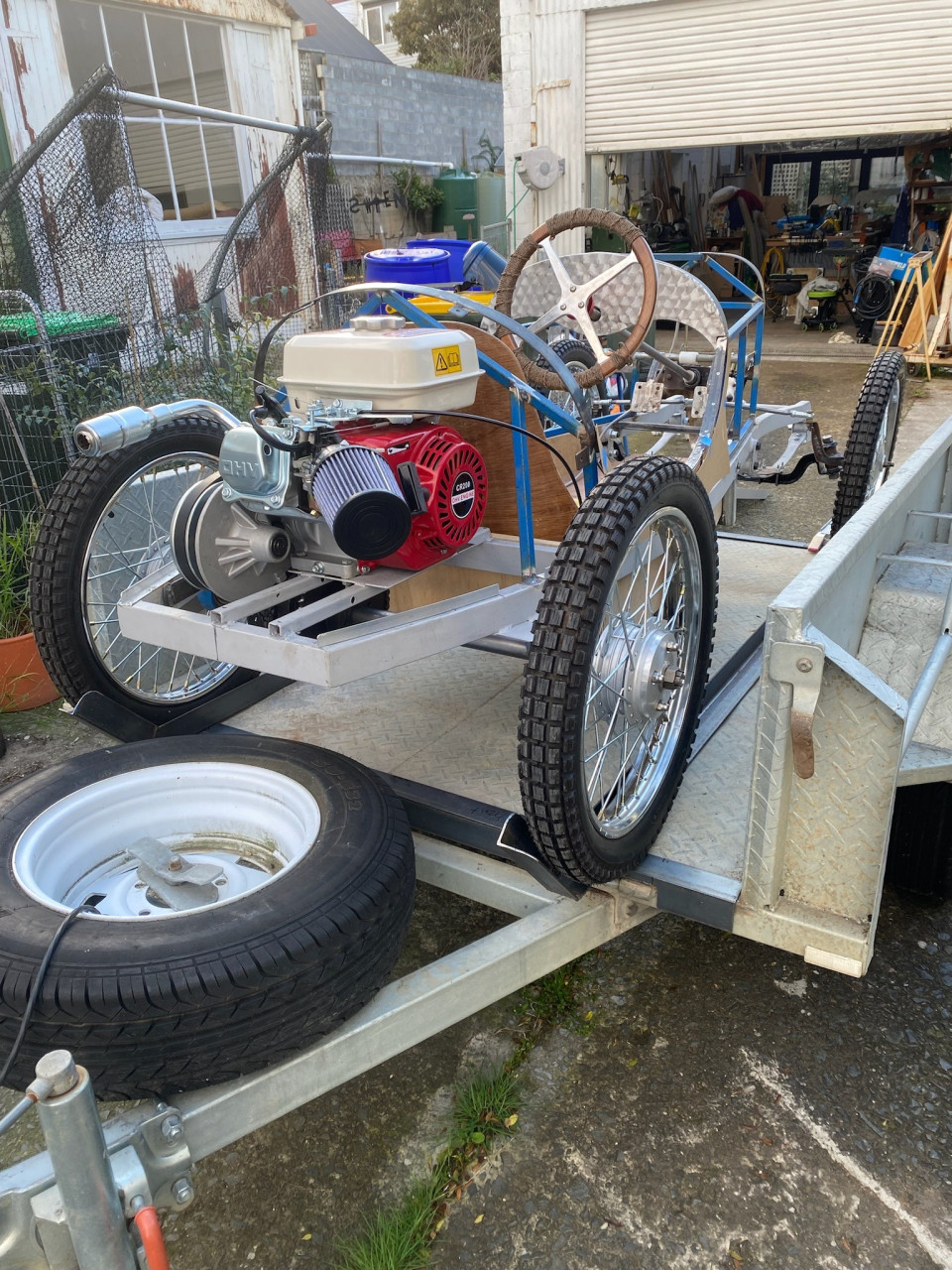
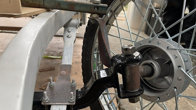
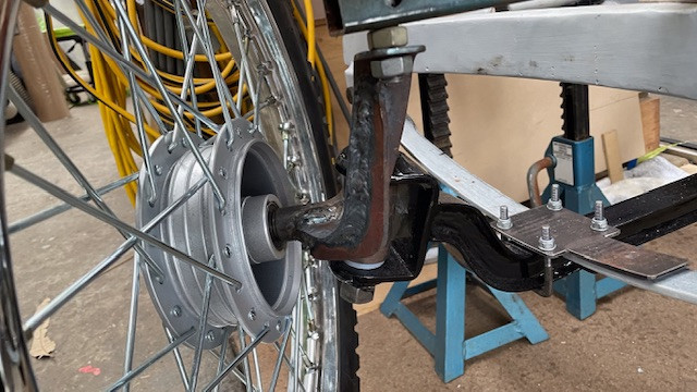
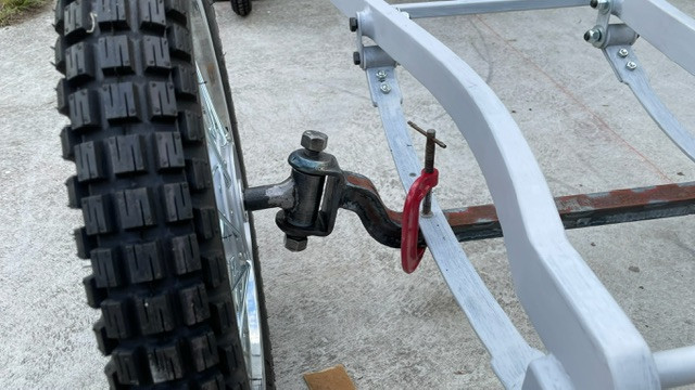
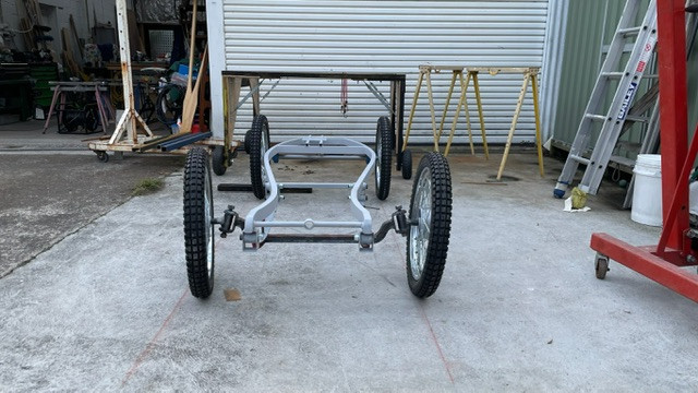
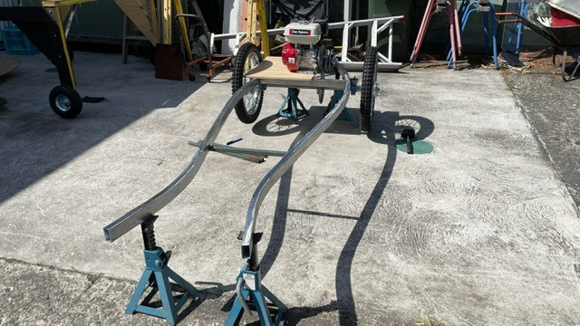
Before the bodywork is progressed too far, we thought it would be a good idea to run the kart and test it out. We decided that the best approach would be to fit a frame into the trailer that will locate the kart wheels and also provide tie down points. The frame was built out of angle iron with some fittings built in so the frame...TransportationMore
Before the bodywork is progressed too far, we thought it would be a good idea to run the kart and test it out. We decided that the best approach would be to fit a frame into the trailer that will locate the kart wheels and also provide tie down points. The frame was built out of angle iron with some fittings built in so the frame can be clamped onto the trailer without the trailer needing to be modified. We are probably using too many tie down straps, but the kart does not move when being trailered.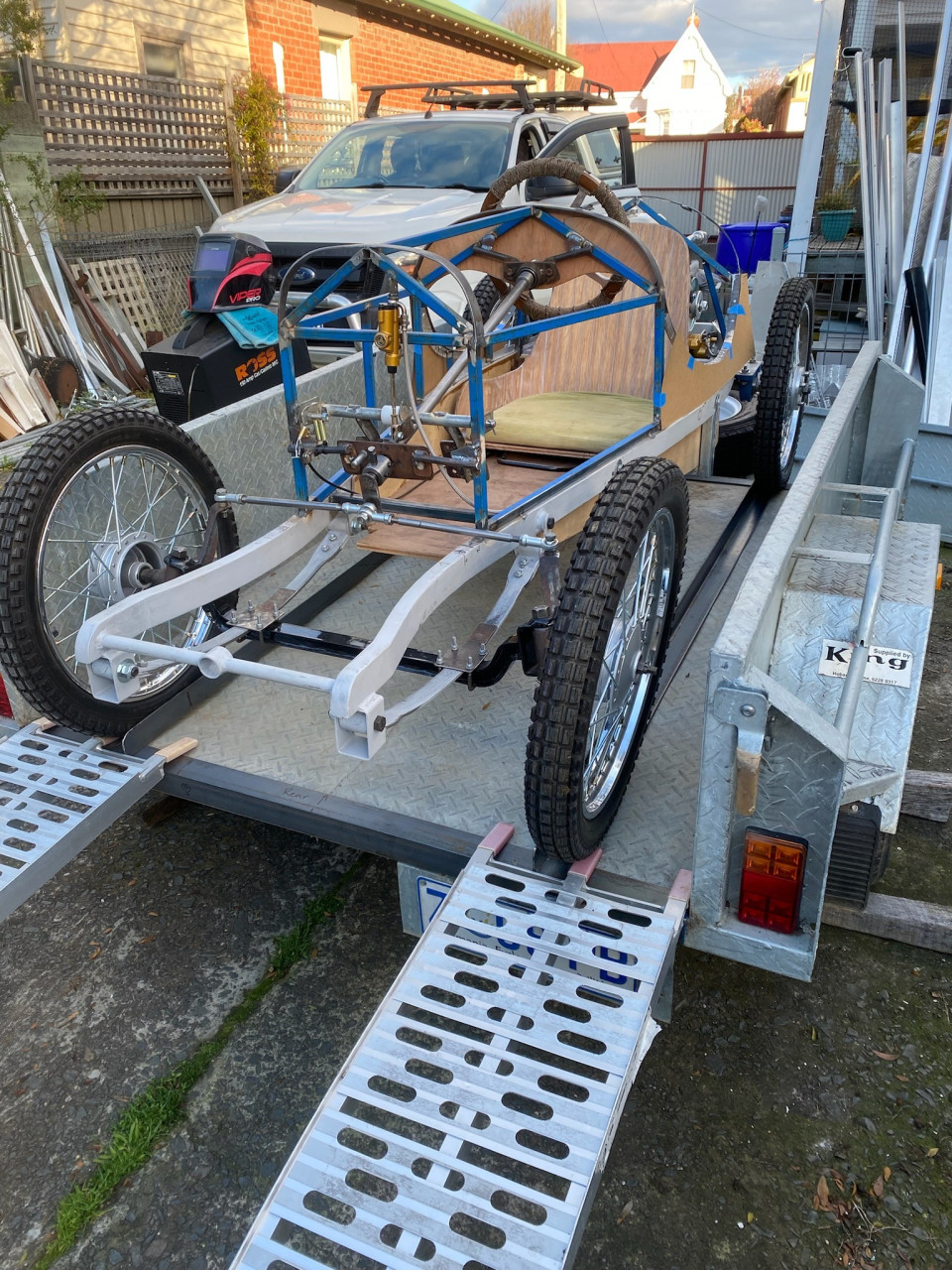
 Comments (2)
-
 Narrowing the springs looks like a great idea I'm guessing easier than cutting them down the middle too.
 -
 We found it useful to narrow the outside of the springs as we could fine tune the spring rate somewhat by cutting off a bit more until they seemed More ...
Post is under moderationStream item published successfully. Item will now be visible on your stream. -
-
BSA Nigel reacted to this post about 1 year agoBodywork
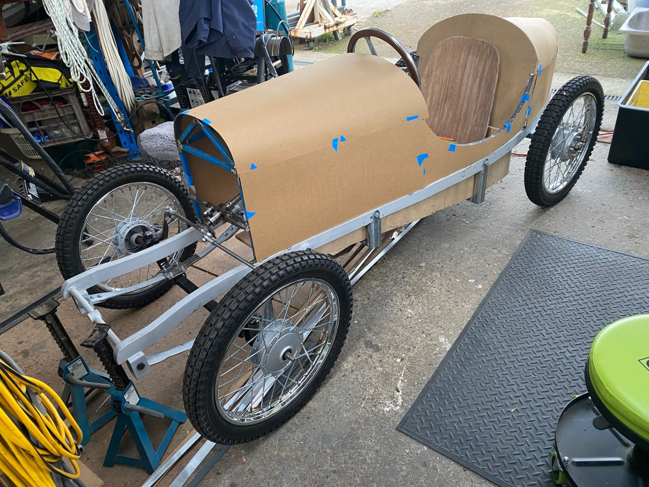
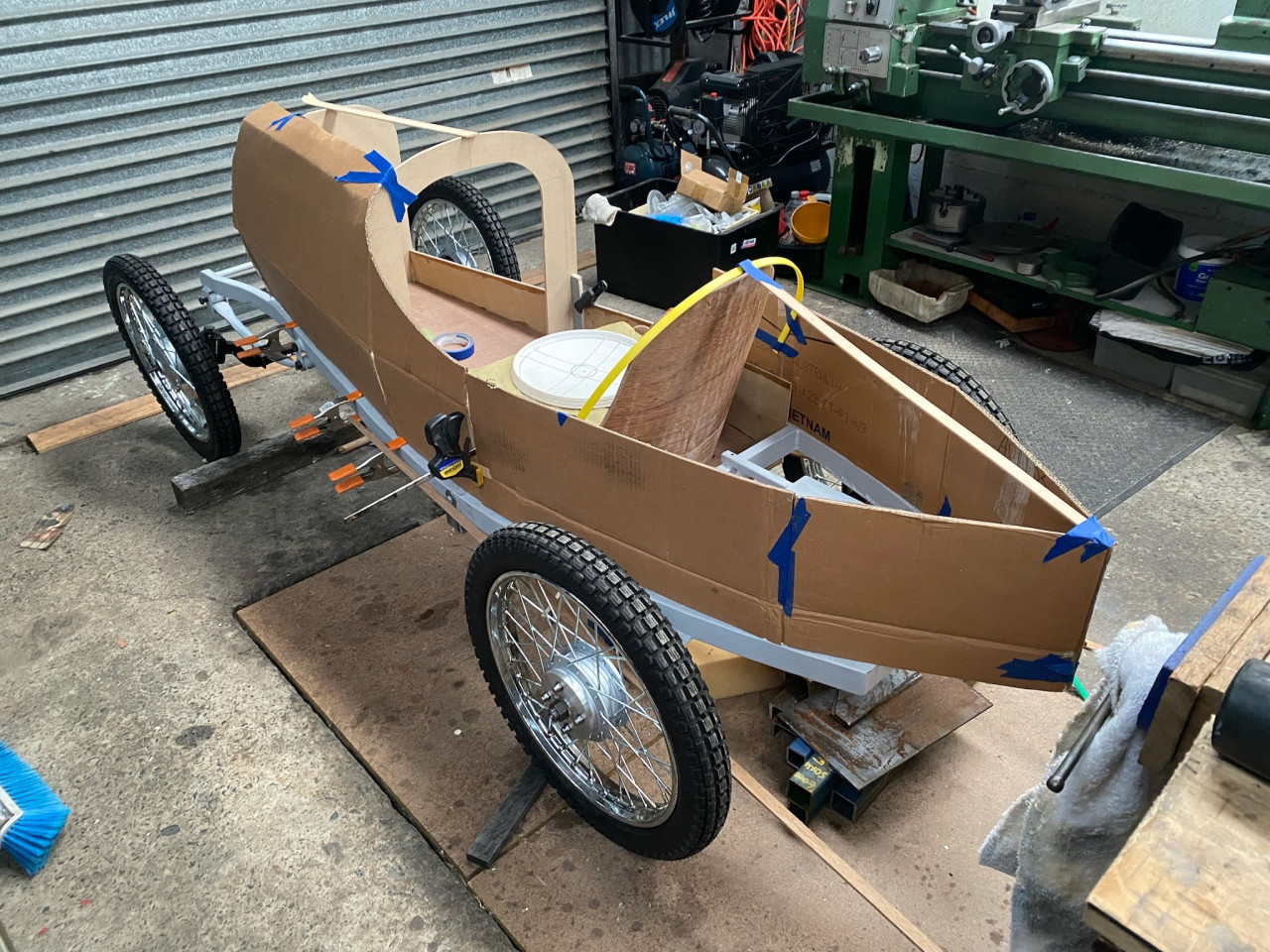
Finally starting to look at the body of the kart. This is where it's really starting to look like something. Cardboard patterns for the panels were made and fitted to the kart. The sides of the 'bonnet' are separate to the top panel of the bonnet. We need the sides to be removable to allow servicing of the foot pedals.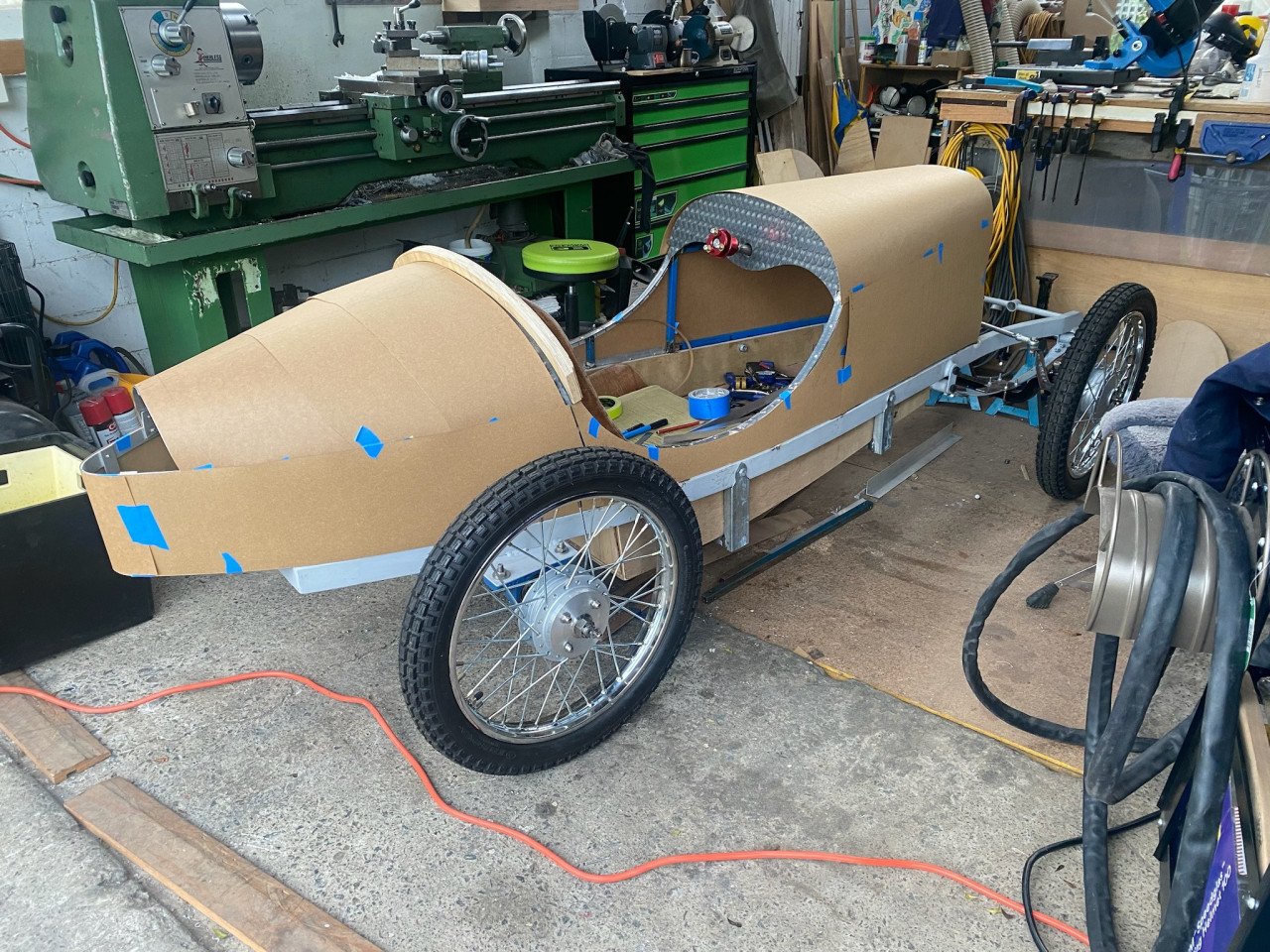
 Post is under moderationStream item published successfully. Item will now be visible on your stream.
 -
Nikki reacted to this post about 1 year agoRadiator
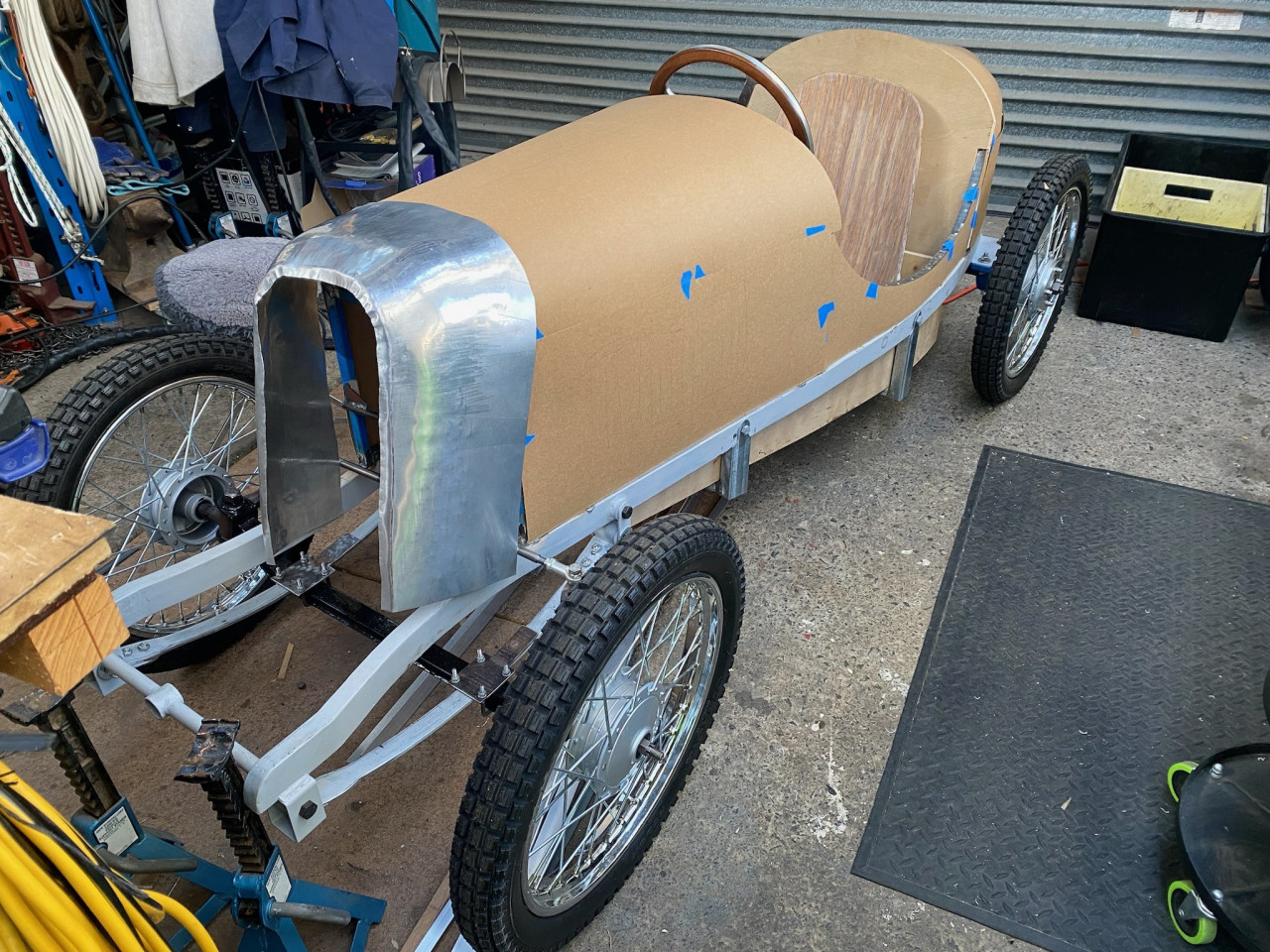
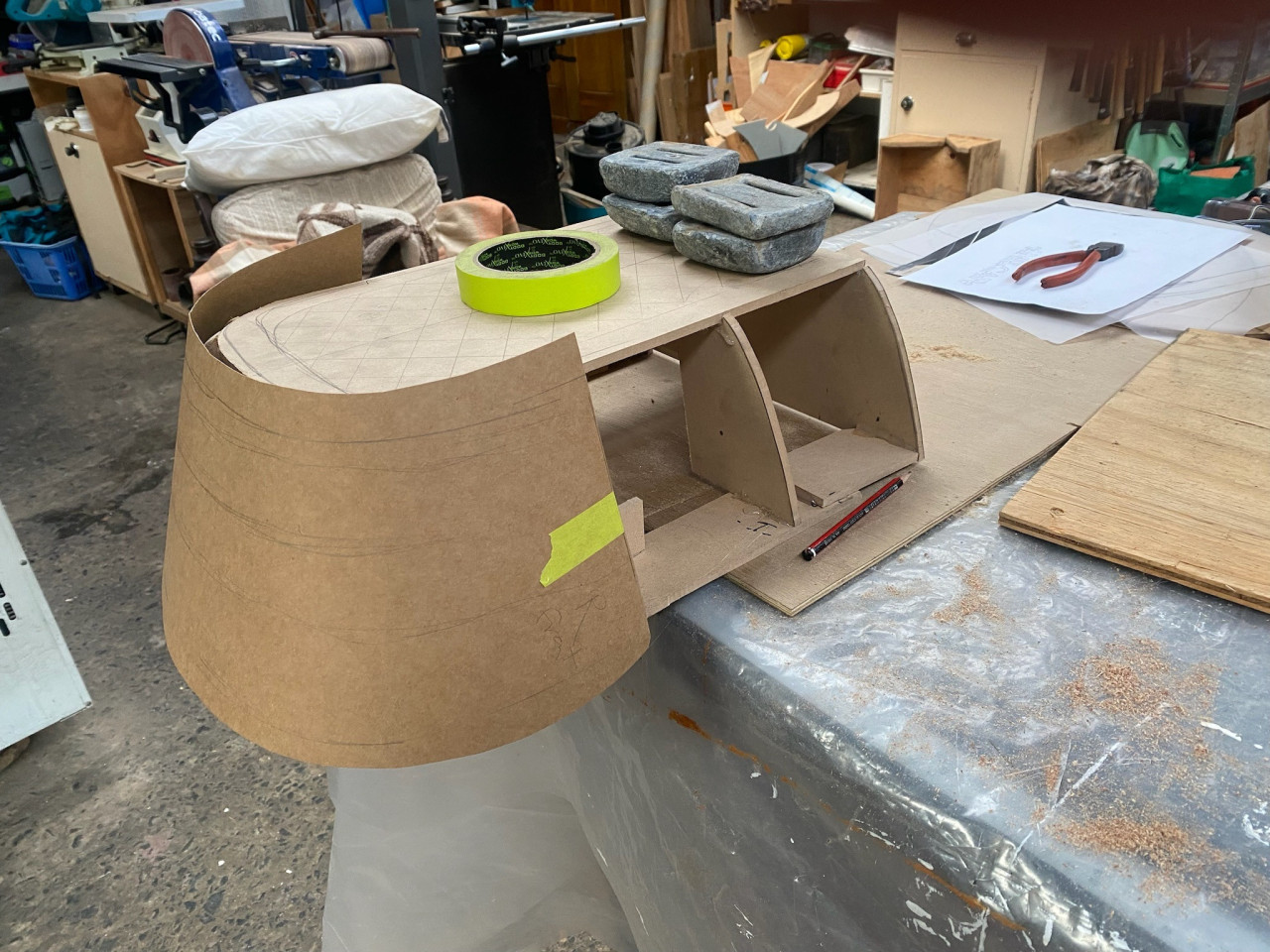
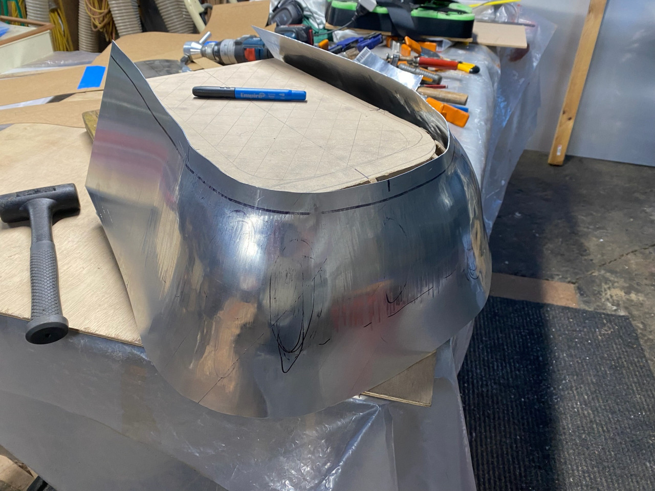
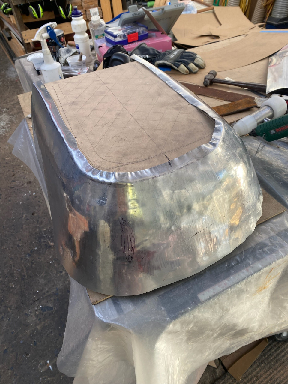
The bodywork around the 'radiator' is probably the most complex panel on the kart. A mock up of the surround was made from MDF so the shape can be tested on the kart. From that a paper template for the alloy sheet was made. This involved a lot of guess work as we don't have a lot of experience with forming aluminium sheet. Nik worked...RadiatorMore
The bodywork around the 'radiator' is probably the most complex panel on the kart. A mock up of the surround was made from MDF so the shape can be tested on the kart. From that a paper template for the alloy sheet was made. This involved a lot of guess work as we don't have a lot of experience with forming aluminium sheet. Nik worked the sheet on the english wheel while comparing the sheet to the shape of the mock up. There is still some fine tuning of the shape to be done but it's really coming along. We found it is useful to anneal the alloy as it work hardens whilst shaping. It's a tricky business as it's very easy to overheat the aluminium.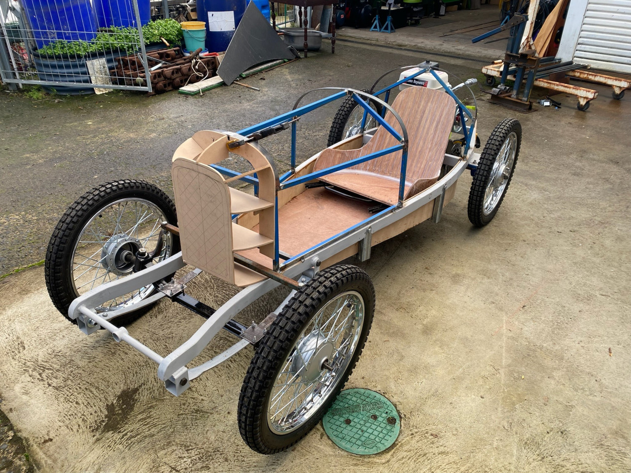
 Post is under moderationStream item published successfully. Item will now be visible on your stream.
 -
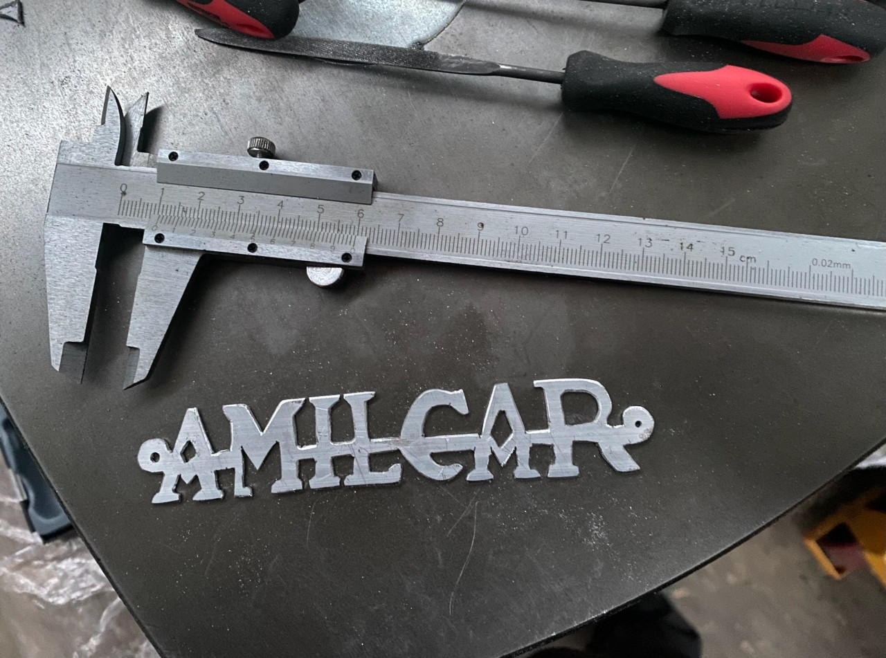
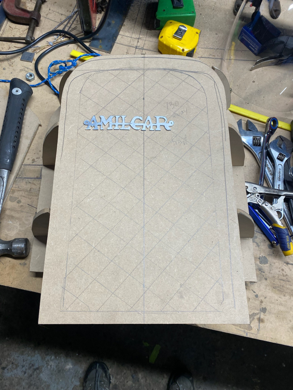
Nikki reacted to this post about 1 year agoRadiator badge
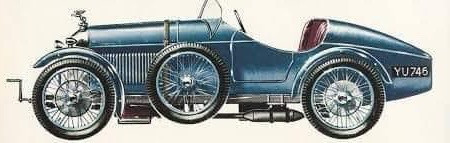
Nik has created a replica Amilcar badge for the radiator by tracing the badge from a photo, then scaling it to a suitable size for the kart and printing out a copy. Glued the print out to a piece of alloy sheet and cut it out using a fret saw. Some cleaning up with jewellers files and it's done.
 Post is under moderationStream item published successfully. Item will now be visible on your stream.
 -
Nikki reacted to this post about 1 year agoImages of the rear bodywork structure. Initial shapes mocked up with welding filler wire then replaced with alloy bar.
 Post is under moderationStream item published successfully. Item will now be visible on your stream.
 -
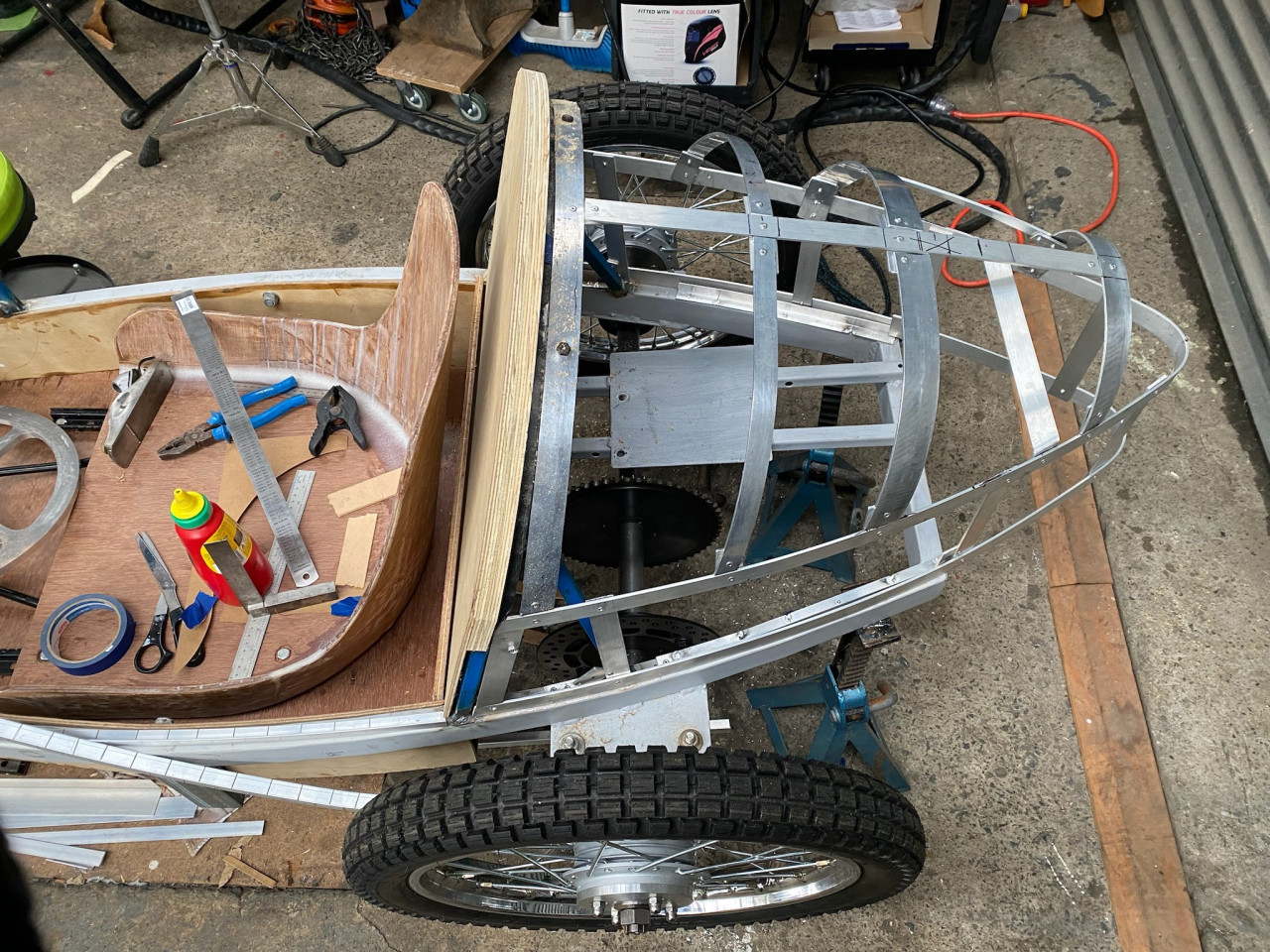
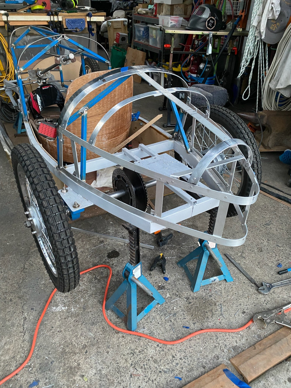
Mick reacted to this post about 1 year agoRear bodywork structure
We’ve used some aluminium bar to create the framework for the rear bodywork. We worked up from the chassis adding elements as we went. The top ‘ribs’ for the bodywork were the most difficult thing to make as they need to be bent in two directions to match the almost conical shape. Some massaging of the bar resulted in...Rear bodywork structureMore
We’ve used some aluminium bar to create the framework for the rear bodywork. We worked up from the chassis adding elements as we went. The top ‘ribs’ for the bodywork were the most difficult thing to make as they need to be bent in two directions to match the almost conical shape. Some massaging of the bar resulted in the supports being able to achieve the required shape.Post is under moderationStream item published successfully. Item will now be visible on your stream. -
Mick commented on this post about 1 year agoWe’ve been busy working on the kart, but not keeping up with posts, so there is some catching up to do.
Bodywork
Some creative full scale CAD work has allowed potential bodywork to be looked at and fine tuned. The clearance of the body around the seat was fine tuned to allow enough elbow space for the driver. The rear bodywork was also looked...We’ve been busy working on the kart, but not keeping up with posts, so there is some catching up to do.More
Bodywork
Some creative full scale CAD work has allowed potential bodywork to be looked at and fine tuned. The clearance of the body around the seat was fine tuned to allow enough elbow space for the driver. The rear bodywork was also looked at to see if there would be enough clearance around the motor and transmission.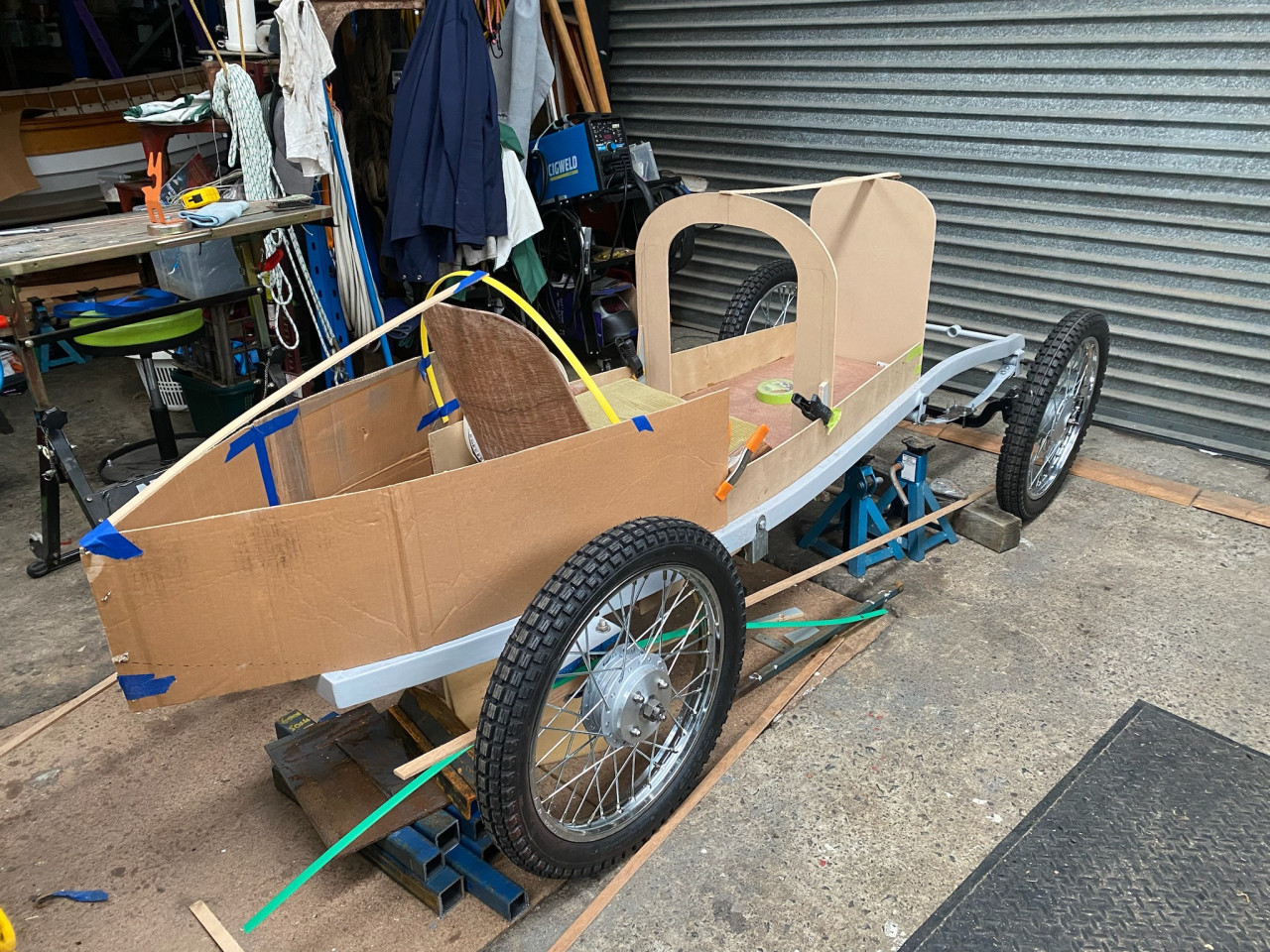
 Post is under moderationStream item published successfully. Item will now be visible on your stream.
 -
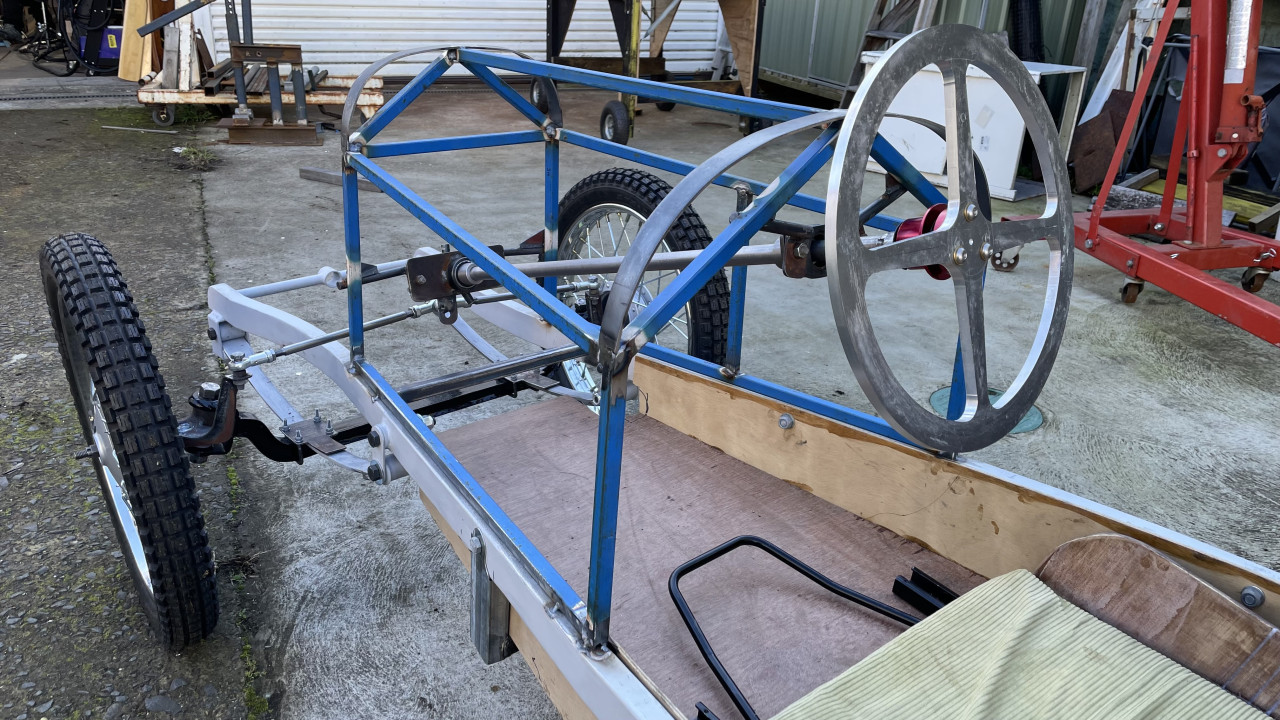
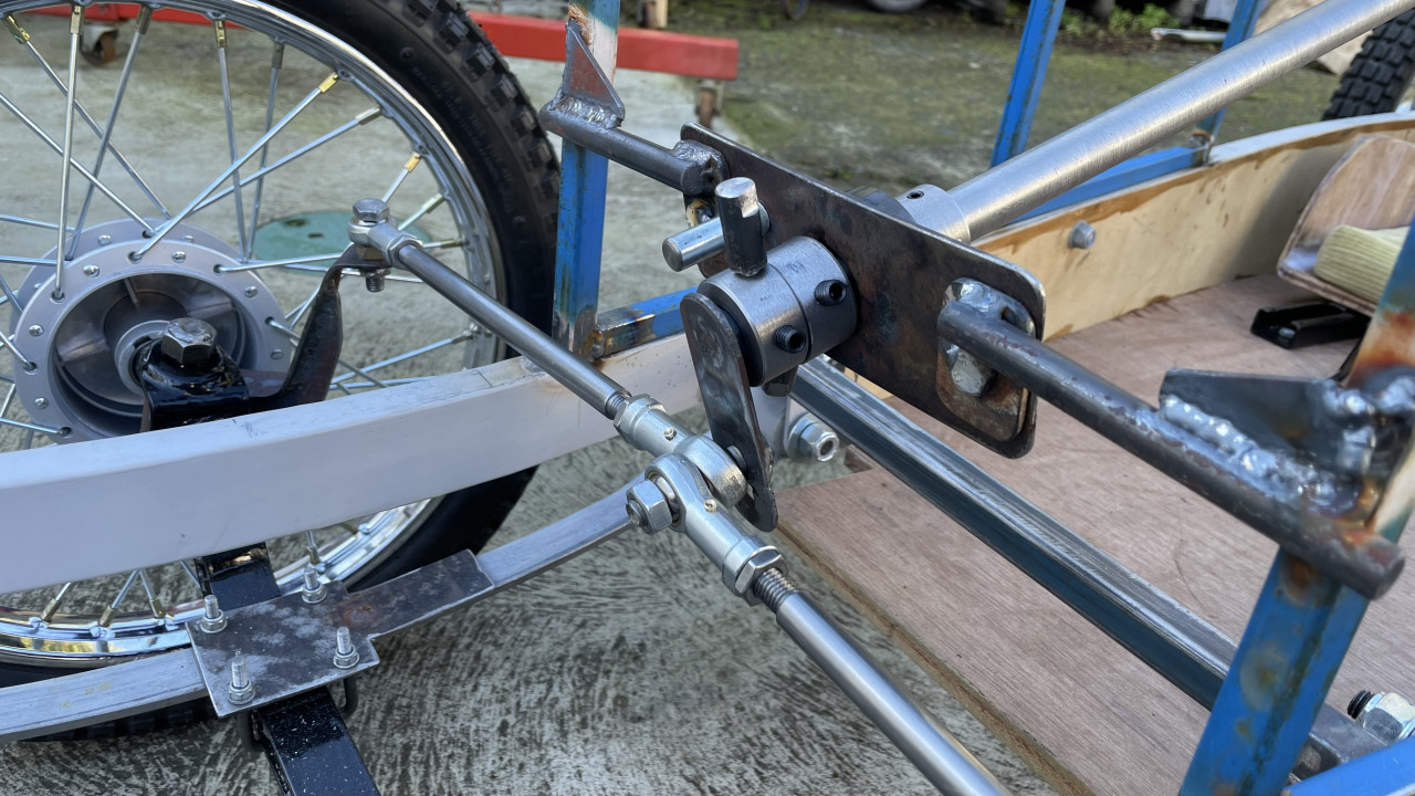
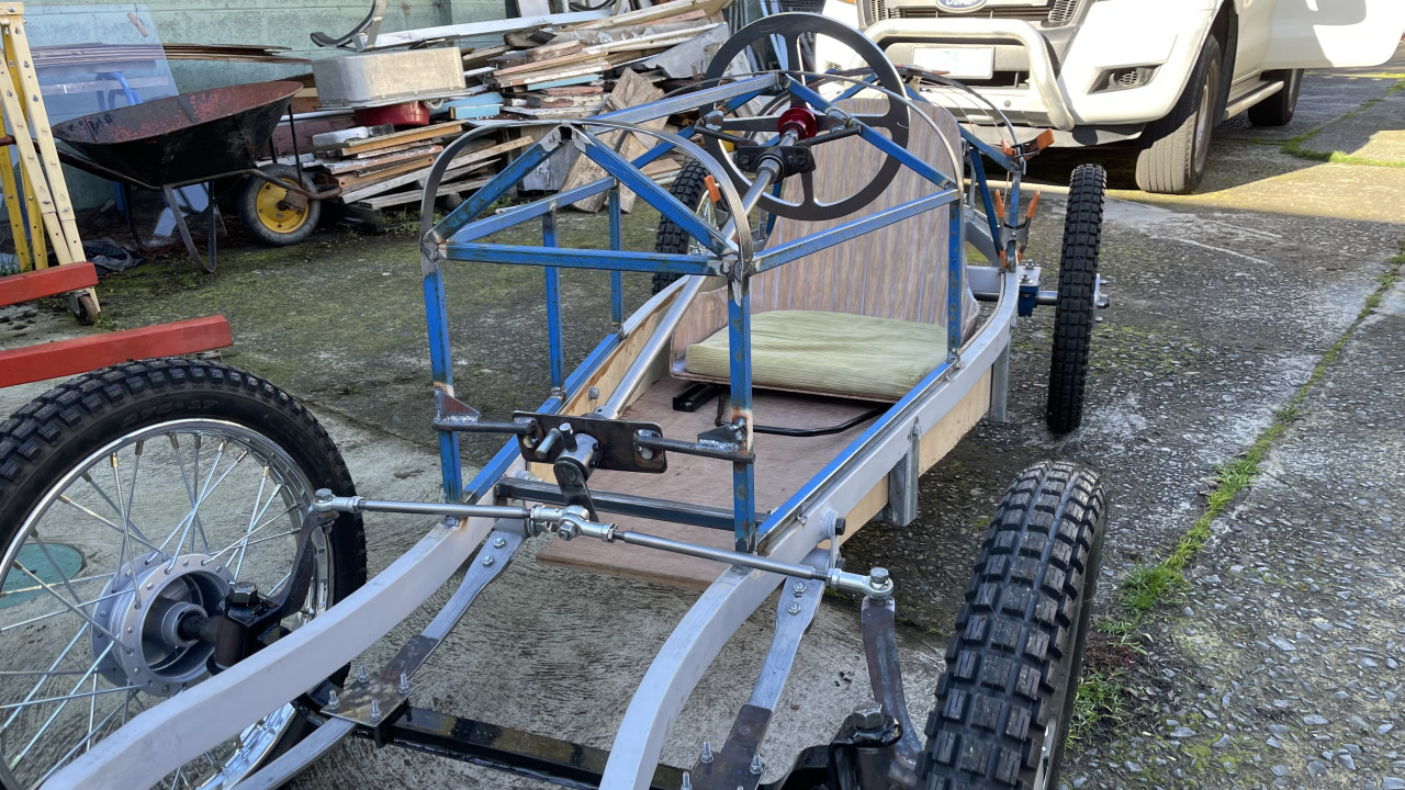
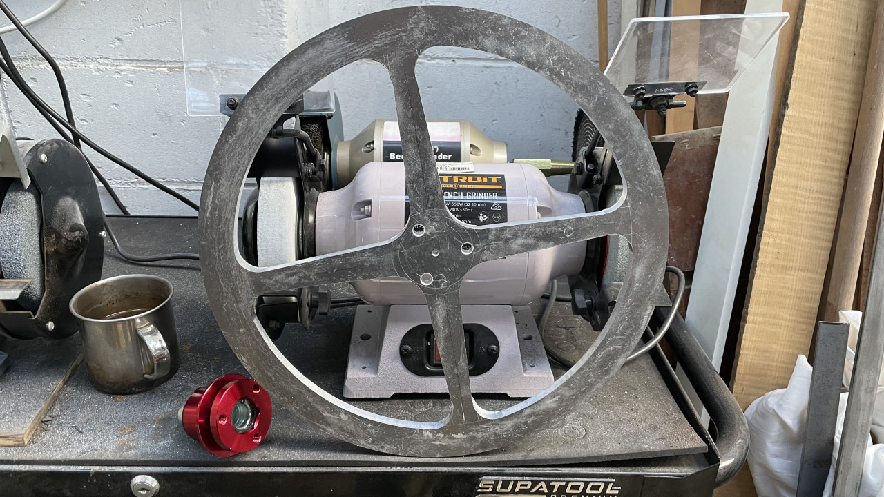
Mick reacted to this post about 1 year agoSteering this week. We’ve decided to make sure it is possible to remove the steering column from the kart if required in the future. To do this, the bearing carriers were attached to plates which are bolted to mounting brackets in the kart. We set up the steering column with the bearings in place before welding the brackets to the kart. ...Steering this week. We’ve decided to make sure it is possible to remove the steering column from the kart if required in the future. To do this, the bearing carriers were attached to plates which are bolted to mounting brackets in the kart. We set up the steering column with the bearings in place before welding the brackets to the kart. Establishing the correct length for the arm at the end of the steering column was a bit of a challenge, but we eventually found a length that works for the steering. A couple of adjustable limit bolts were added to ensure the steering doesn’t go past centre. The steering wheel as it is in the photos is the centre blank which has been machined from aluminium. The wheel will be finished off in time with some timber to form the outer grip. The wheel’s spokes will also be rounded a little to soften up the edges. We’ve decided to use a quick release hub for the steering wheel to facilitate getting in and out of the kart. The unit was found on eBay and has so far impressed us with its build quality and positive function. After assembling the steering some initial adjustment of the length of the control arms resulted in the kart steering quite well. During turns there isn’t any discernible scrubbing of the front tyres. If this style of steering proves to be too ‘fast’ resulting in a nervous ride, we might look at a more conventional steering rack.More
 Post is under moderationStream item published successfully. Item will now be visible on your stream.
 -
 Post is under moderationStream item published successfully. Item will now be visible on your stream.
 -
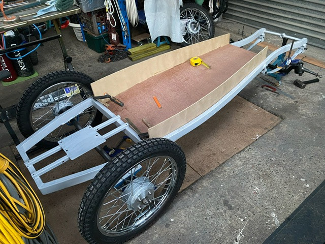
Floor pan. The floor pan was build out of plywood with thin ply sides. The pan has about a 10cm tilt relative to the chassis. The pan has been dropped below the level of the chassis to lower the centre of gravity of the car. Two steel rails running crossways under the floor pan provide support. The rails are bolted on to allow the pan to be...Floor pan. The floor pan was build out of plywood with thin ply sides. The pan has about a 10cm tilt relative to the chassis. The pan has been dropped below the level of the chassis to lower the centre of gravity of the car. Two steel rails running crossways under the floor pan provide support. The rails are bolted on to allow the pan to be removed as required.More
 Post is under moderationStream item published successfully. Item will now be visible on your stream.
 -
Steering arms. After getting the front axle into place, we looked at the steering arms. The goal was to get the steering components above the chassis rails to ensure clearance through the full suspension travel. Some CAD work resulted in patterns for the steering arms and their supporting struts. The location of the steering bolt is inline...Steering arms. After getting the front axle into place, we looked at the steering arms. The goal was to get the steering components above the chassis rails to ensure clearance through the full suspension travel. Some CAD work resulted in patterns for the steering arms and their supporting struts. The location of the steering bolt is inline with the steering knuckle axis and the mid point of the rear axle to create Ackerman steering geometry. Some bending of steel and dubious welding and it’s done. A bit of grinding then painting should tidy up the arms. We have fitted a temporary rod between the steering arms to keep the front wheels under control until the steering is completed. There was no discernible scrubbing of the front tyres during testing of the steering.More
 Post is under moderationStream item published successfully. Item will now be visible on your stream.
 -
 Post is under moderationStream item published successfully. Item will now be visible on your stream.
 -
Post is under moderationStream item published successfully. Item will now be visible on your stream.
-
 Post is under moderationStream item published successfully. Item will now be visible on your stream.
 -
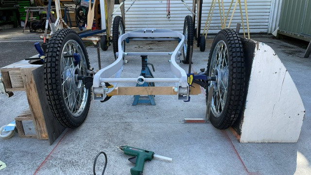
Mick reacted to this post about 1 year agoFront beam axle. With the chassis sitting on its rear wheels and level, the front wheels were propped up so the steering hubs were at the right castor and camber angles for the build. We’ve selected a castor value on the high side of typically recommended values to bias the steering towards tracking stability. With the wheels set at the right...Front beam axle. With the chassis sitting on its rear wheels and level, the front wheels were propped up so the steering hubs were at the right castor and camber angles for the build. We’ve selected a castor value on the high side of typically recommended values to bias the steering towards tracking stability. With the wheels set at the right angles, a pattern capturing the locations of the bottom of the springs and the steering knuckles was made using fibreboard and hot glue. With the pattern capturing the geometry the beam axle was built up from square steel tubing, steel plate cut to the shape of the curves up to the knuckles and steel strap top and bottom to tie everything together. After the beam was fabricated, we set the wheels up again to check the geometry was right then tacked the steering joints to the beam. With the wheels attached the kart could be rolled forwards despite the wheels not being tied together. We took that as a sign that the castor of the steering will work for us.More
 Post is under moderationStream item published successfully. Item will now be visible on your stream.
 -
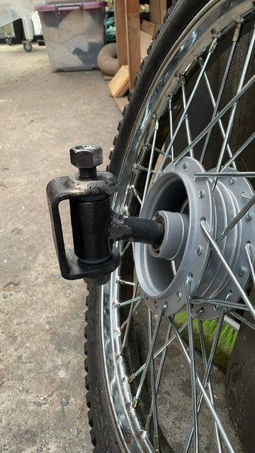
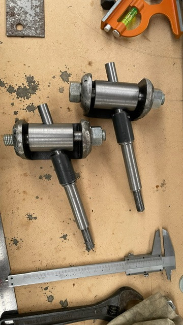
Nikki reacted to this post about 1 year agoSteering knuckles. Axles machined out of mild steel rod and run through the steering knuckle itself. We adopted this approach to ensure there is plenty of support for the axles. Knuckles have nylon bushings top and bottom to provide a bearing surface for the retaining bolts. The angle of the axle looks extreme, but is in line with other builds...Steering knuckles. Axles machined out of mild steel rod and run through the steering knuckle itself. We adopted this approach to ensure there is plenty of support for the axles. Knuckles have nylon bushings top and bottom to provide a bearing surface for the retaining bolts. The angle of the axle looks extreme, but is in line with other builds seen online. Being first time builders, we’ve gone for strength over light weight.More
 Post is under moderationStream item published successfully. Item will now be visible on your stream.
 -
Follow our Facebook page and connect with other Cyclekartistes
-
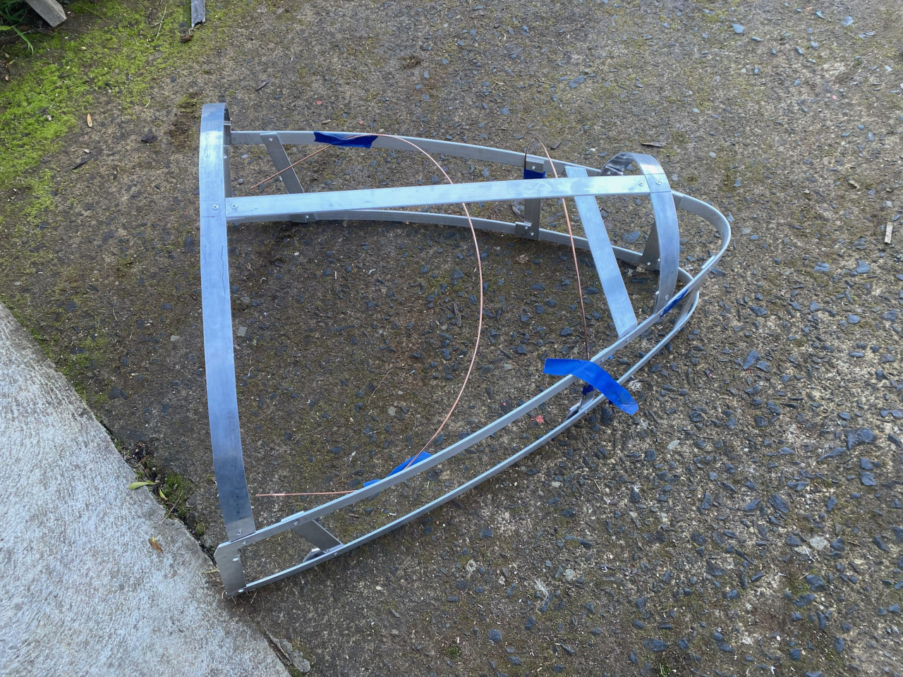
Nikki reacted to this post about 1 year agoChassis start. The outline of the chassis was scaled up from photographs and drawn onto a large sheet of fibreboard with the locations of major components also drawn on to check that the build will be more or less compliant with the guidelines for Cyclekarts. The chassis rails are 75x25mm steel box section which where shaped by slicing...Chassis start. The outline of the chassis was scaled up from photographs and drawn onto a large sheet of fibreboard with the locations of major components also drawn on to check that the build will be more or less compliant with the guidelines for Cyclekarts. The chassis rails are 75x25mm steel box section which where shaped by slicing segments out of the box section to allow the rails to bend and follow the outline drawn onto the fibreboard. The rails were then secured to the board and the segments TIG welded back up to fix the final shape. This approach was selected due to the lack of facilities to roll form the rails.More
Second image shows the chassis from the rear with engine supports in place.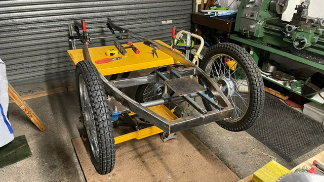
 Post is under moderationStream item published successfully. Item will now be visible on your stream.
 -
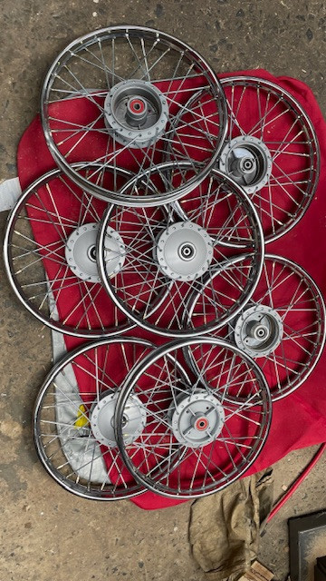
Mick reacted to this post about 1 year agoWheels! 17 inch wheels, sourced online. Quality appears to be reasonable though they are not 100% true. Bearings will be replaced with ones which allow for larger diameter axles.
 Post is under moderationStream item published successfully. Item will now be visible on your stream.
 -
Nikki reacted to this post about 1 year agoCreating a new page for the Amilcar build. We will add entries to the time line to roughly approximate the stages of the build.Post is under moderationStream item published successfully. Item will now be visible on your stream.
-
Stream item published successfully. Item will now be visible on your stream.
There are no activities here yet
HowThat looks fantastic. Thanks for sharing. This is something that I need to do on my car. The Bentley seems to be more louvres than bonnet lol.
How much force do you think it took? I have a small 1 ton arbour press here, wondering if it would be big enough More ...