
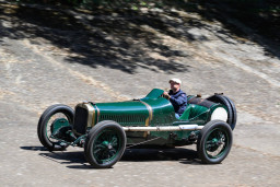
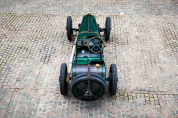
CycleKarts
CycleKarts are vehicles that have been built according to the Cyclekart Club of Australia rules.
- 32 pages
- 10 Albums
Pinned Items
Recent Activities
-
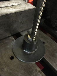
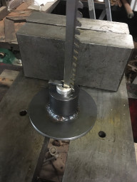
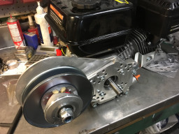
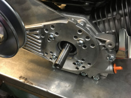
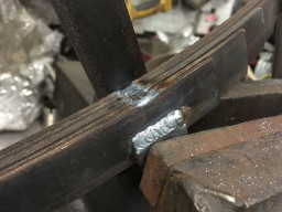
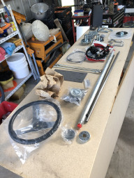
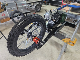
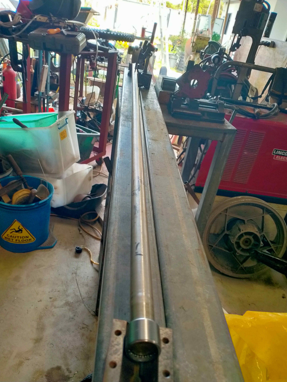
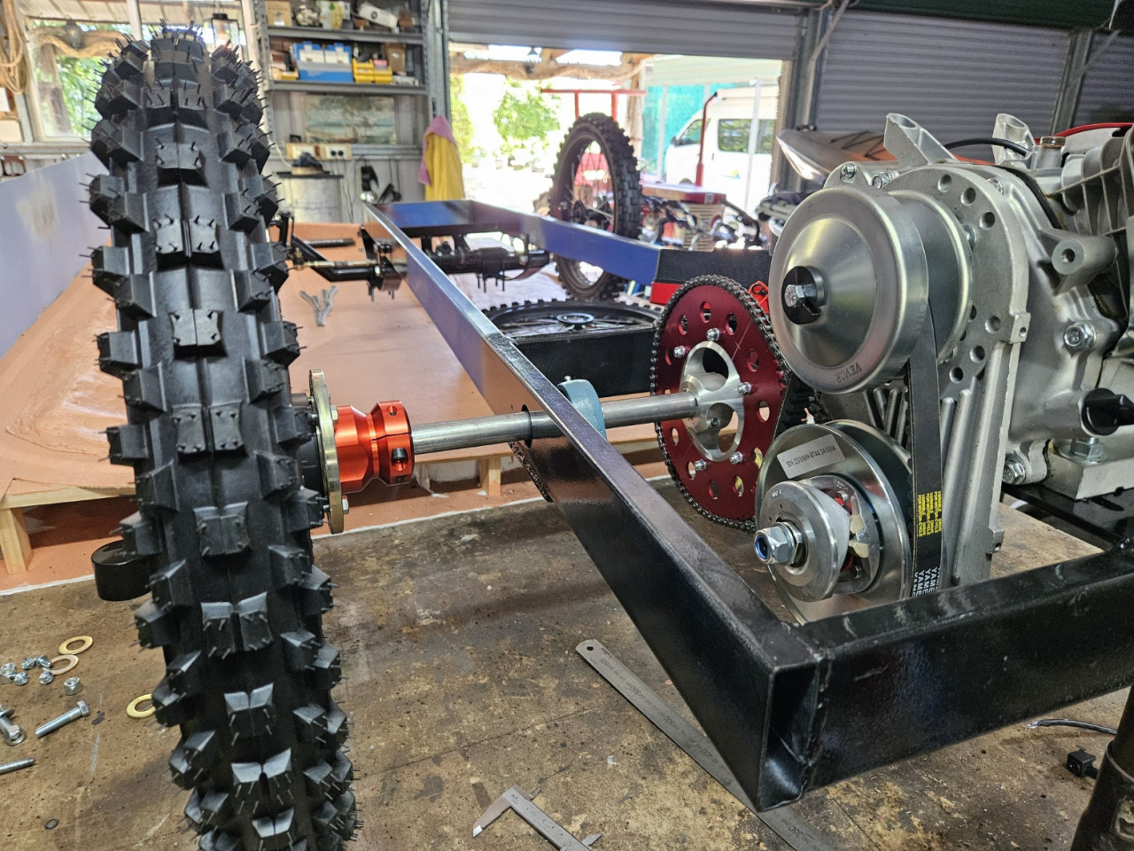
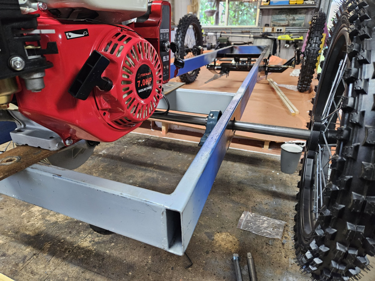
Pursang's "Vintage Morgan" Inspired 3 Wheeler. reacted to this post about 1 month agoFound a new use for the shaft fixture used when cutting the key ways.
Shaft is aligned squarely and straight to the engine mounting plate and output shaft.
 Post is under moderationStream item published successfully. Item will now be visible on your stream.
 -
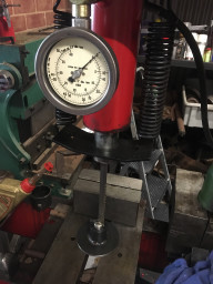
Pursang's "Vintage Morgan" Inspired 3 Wheeler. reacted to this post about 1 month agoAfter cutting the key ways, it turned out that the shaft (bought new) was actually spaghetti.
Visibly plus or minus 1mm at several points along it's 1300mm length.
I set it up in needle roller bearings and V-blocks, then measured and massaged it to nearly straight.
Biggest variation is now 0.1mm (around 0.004".), hopefully this will be...After cutting the key ways, it turned out that the shaft (bought new) was actually spaghetti.More
Visibly plus or minus 1mm at several points along it's 1300mm length.
I set it up in needle roller bearings and V-blocks, then measured and massaged it to nearly straight.
Biggest variation is now 0.1mm (around 0.004".), hopefully this will be sufficient.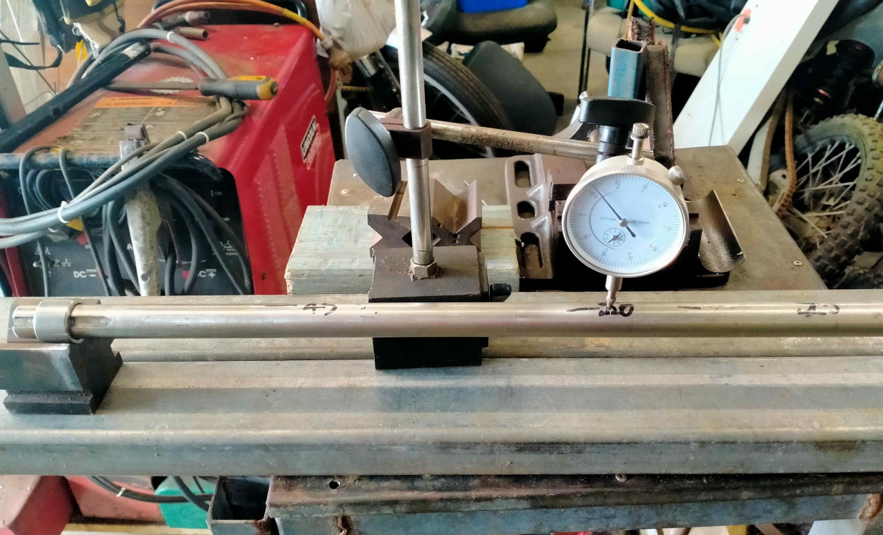
 Post is under moderationStream item published successfully. Item will now be visible on your stream.
 -
kjacml@yahoo.com.au reacted to this post about 3 weeks agoMore photos of the buildPost is under moderationStream item published successfully. Item will now be visible on your stream.
-
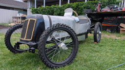
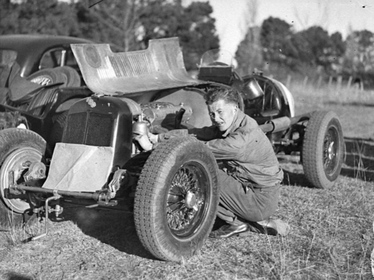
Pete_R reacted to this post about 1 month agoSome historical photos of the build...Post is under moderationStream item published successfully. Item will now be visible on your stream.
-
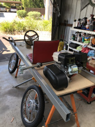
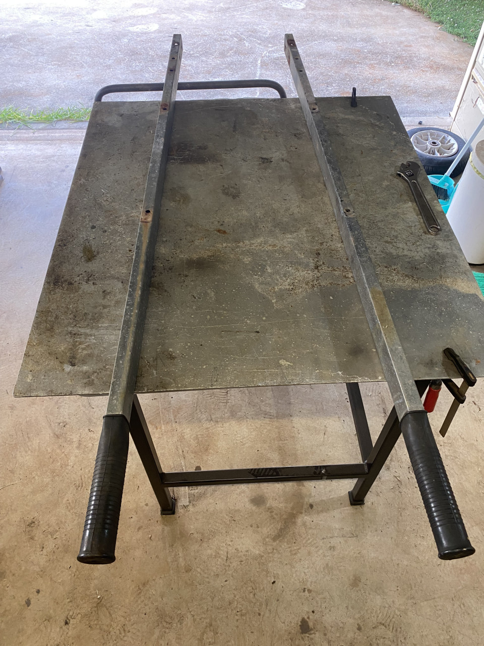
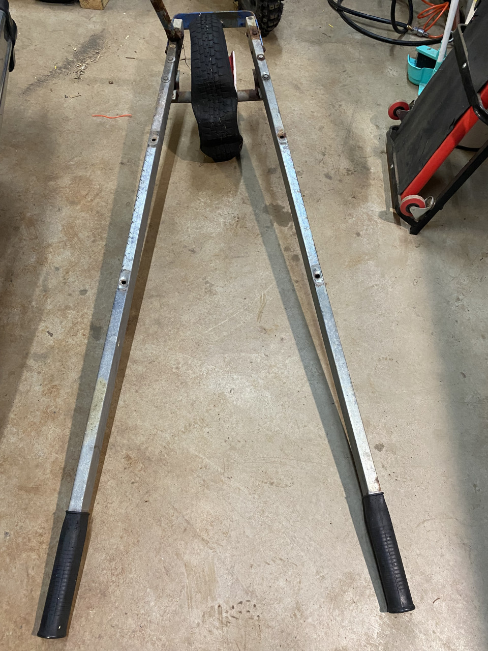
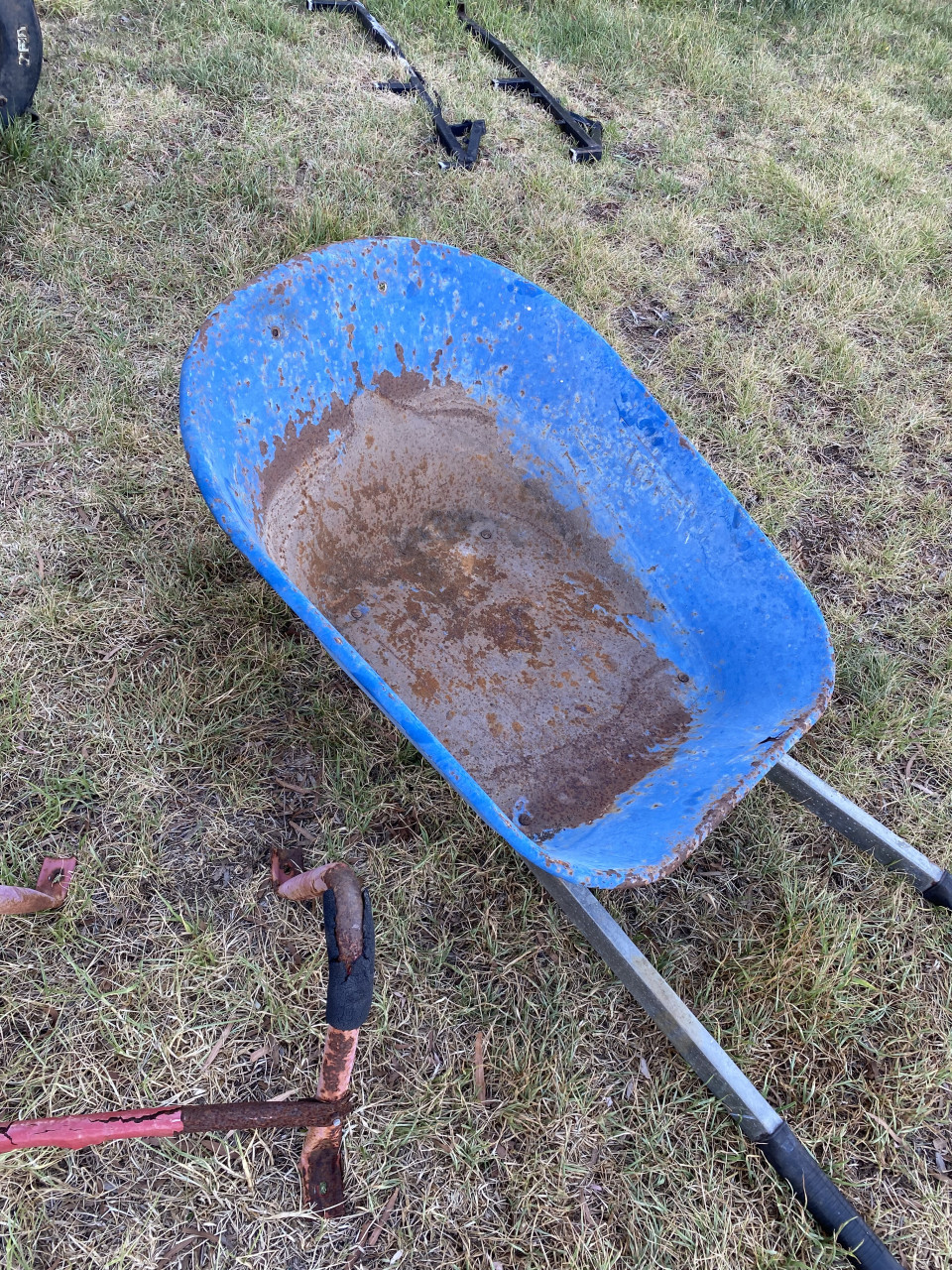
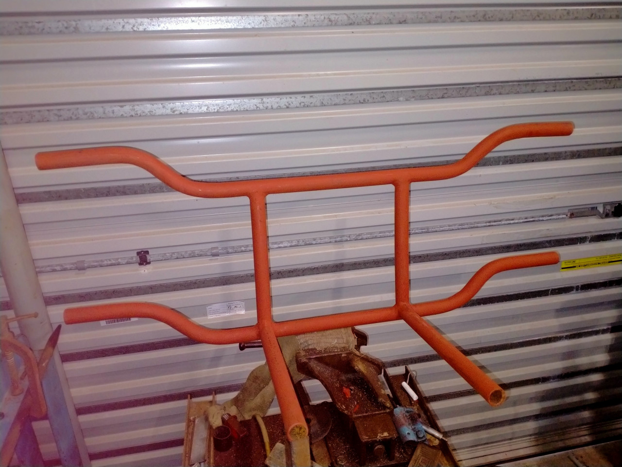
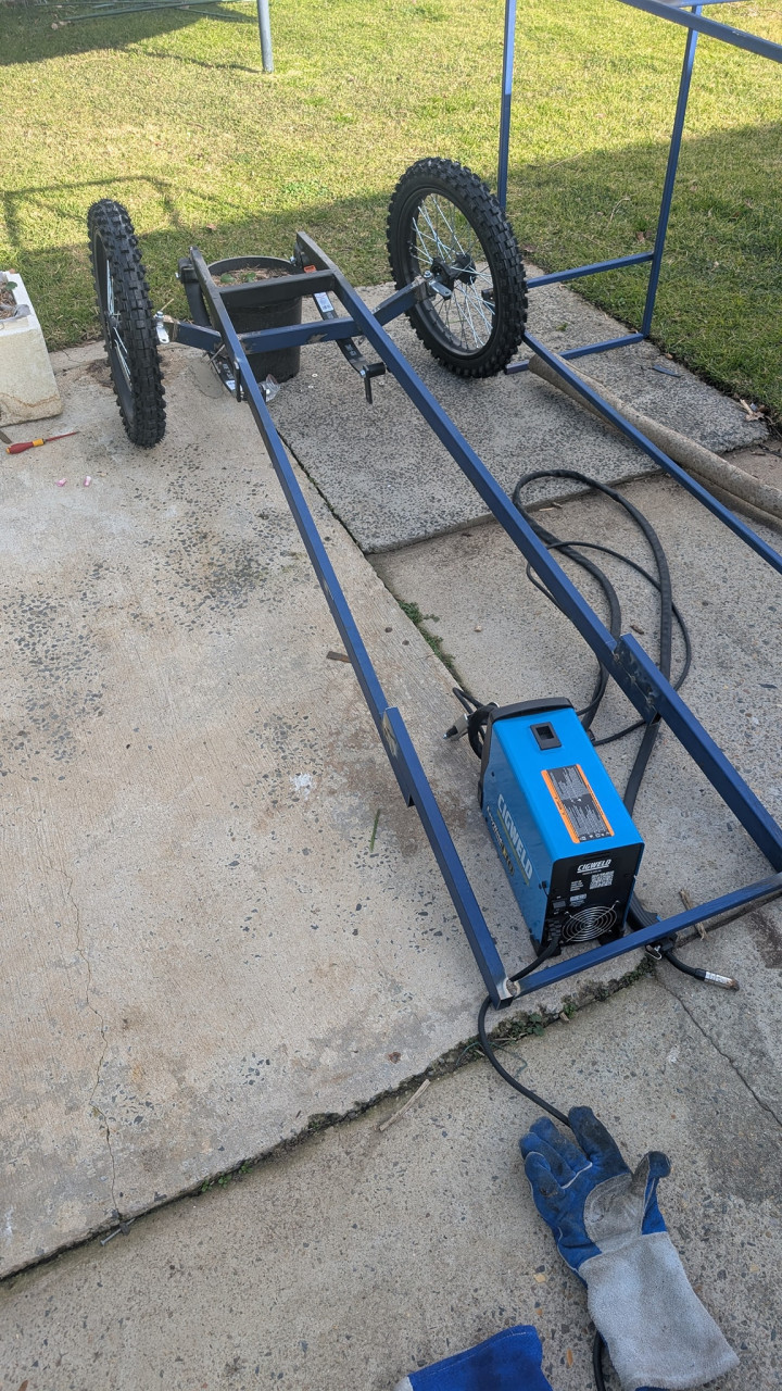
kjacml@yahoo.com.au reacted to this post about 3 weeks agoStep one. Wheelbarrow handles as the chassis side rails.
 Comments (2)
-
 Can't wait to see what you come up with
 -
 Love it
Post is under moderationStream item published successfully. Item will now be visible on your stream. -
-
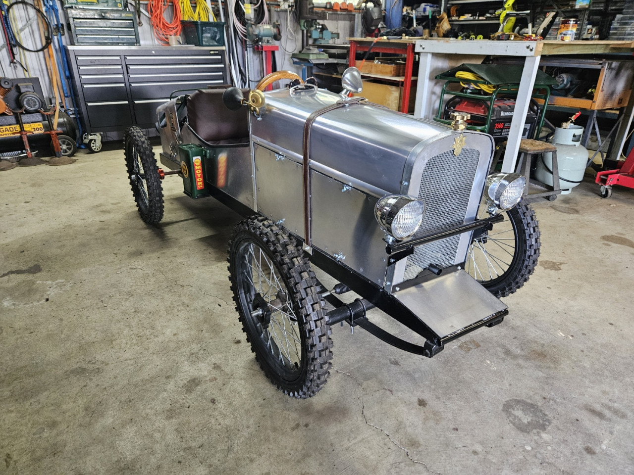
kjacml@yahoo.com.au reacted to this post about 1 month agoWork, Life and organising events really slowed down the progress on my build. Whilst not being ruinning by the NSW BBQ Event, I got enough done to be able to showcase what I have been up to and to give people an idea on the build process of a cyclekart.
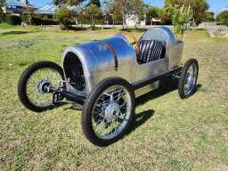
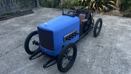
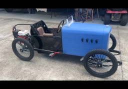
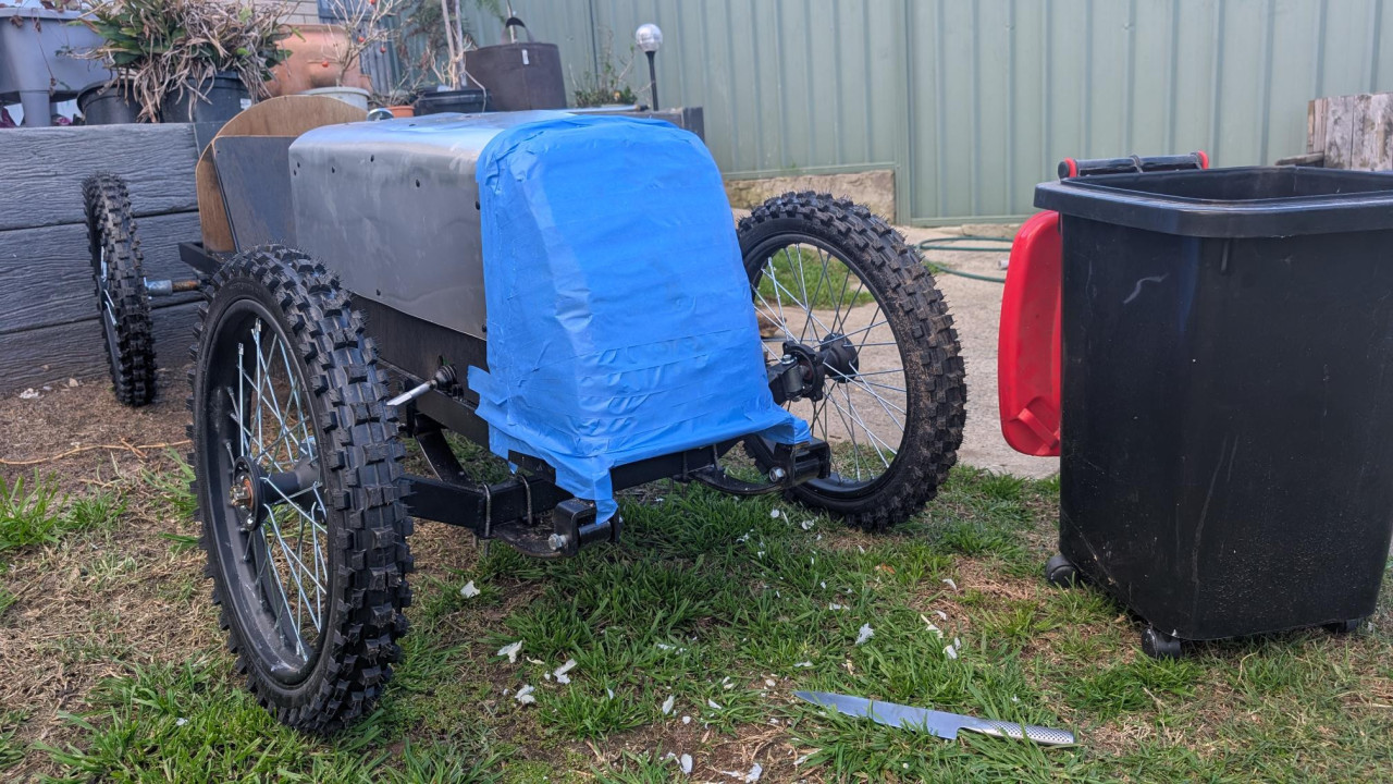
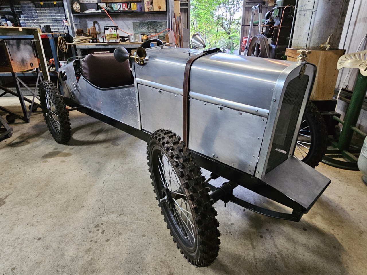
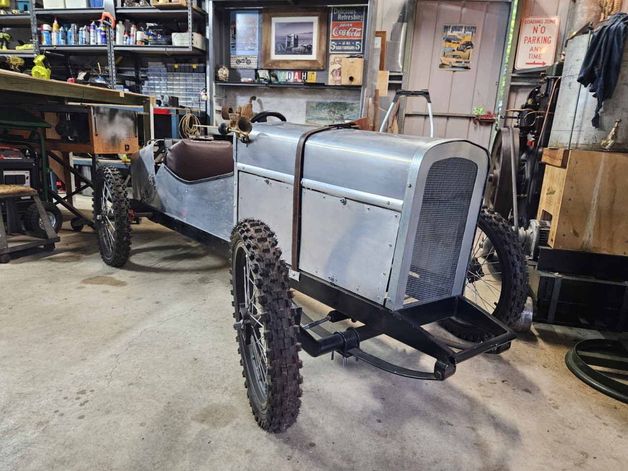
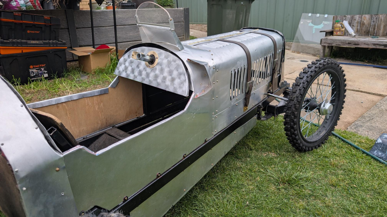
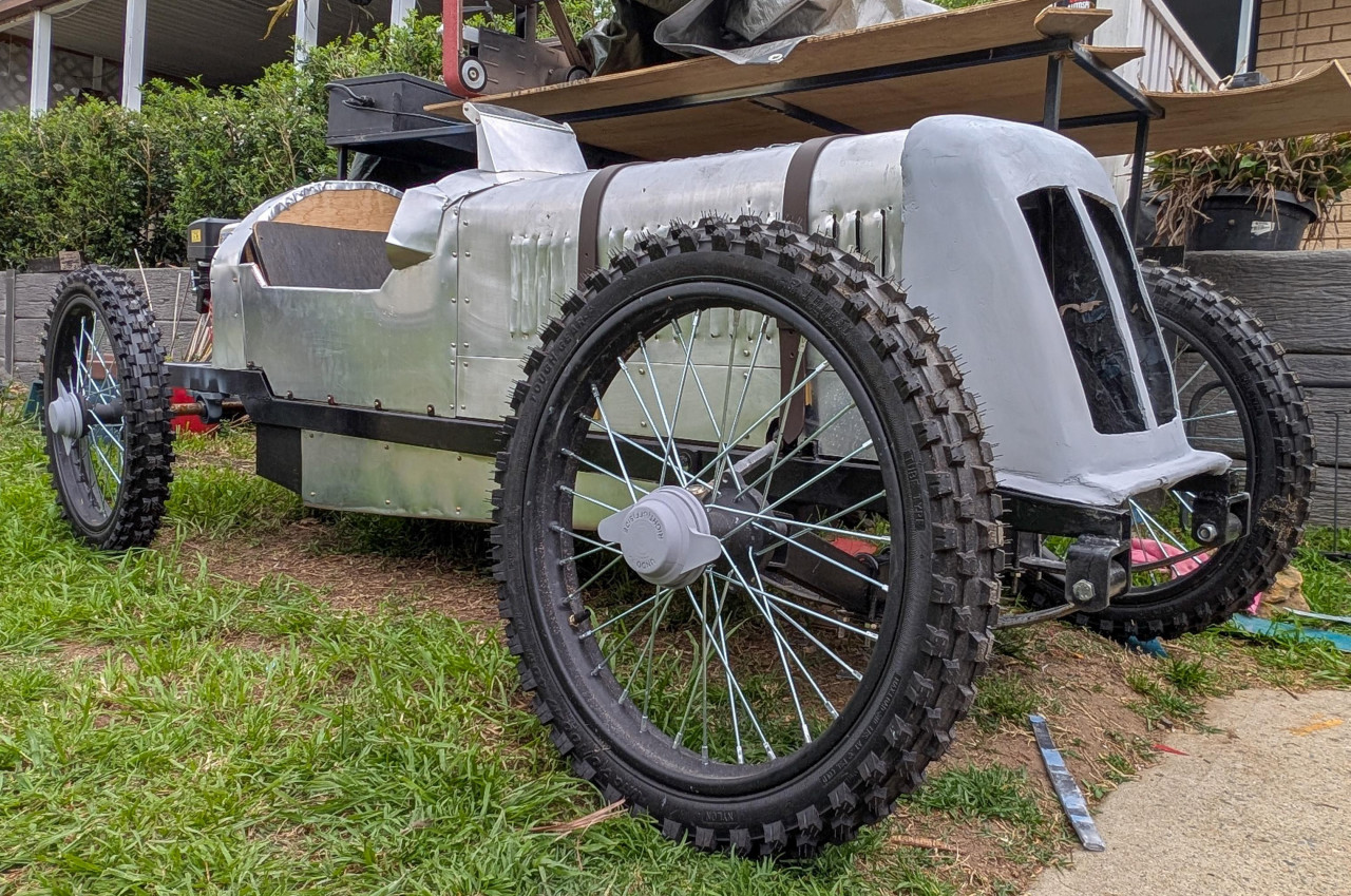
Since the last update, I have completely skinned the front 2/3s of the kart in 0.5mm...Work, Life and organising events really slowed down the progress on my build. Whilst not being ruinning by the NSW BBQ Event, I got enough done to be able to showcase what I have been up to and to give people an idea on the build process of a cyclekart.More
Since the last update, I have completely skinned the front 2/3s of the kart in 0.5mm aluminium and punched about 3/4 of the louvre vents. I made an assortment of punches out of scrap plywood and old merbau timber decking. I used the merbau to make punches and then made dies out of 12mm plywood. It works well enough on the thin aluminium - the dies are stronger than the sheet itself and will split it if you aren't careful.
Ive made a lot of progress on the fibreglass nosecone. I've smoothed it out, put the front cutouts in, painted it and started making a grille. Though not quite finished as a I would like, I have made big progress.
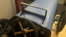
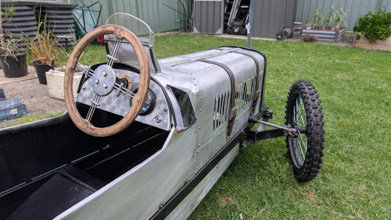
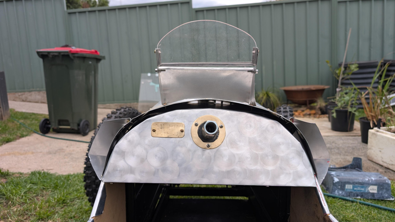
I have made a dashboard from 12mm ply which i have skinned with aluminium and dressed with brass. It contains my keyed electric start ignition and an 85mm GPS speedometer. For 12v power, I got a Milwaukee M12 battery adapter that tucks up behind the dash out of sight to power the 12v accessories.
Steering wheel is about half way done and roughed in to shape. It is made from lasercut 3mm steel and clad in 12mm Plywood with Red 1mm G10 liners between the wood and steel which I had left over from my bladesmithing escapades
Ive also started on the windscreen and side view mirrors which are a work in progress.
Whilst Im a long way off completion, I am hoping to get a lot more done before the Goulburn Car show in NovemberPost is under moderationStream item published successfully. Item will now be visible on your stream. -
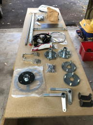
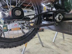
kjacml@yahoo.com.au reacted to this post about 1 month agoSome updates over the last few days. Removed the lugs from the inside of the front wheels so that the wheel fits with the lugs ion the inside and the lugs don't interfere with the steering arm. Fitted grease nipples to the steering king pins and removed some of the vertical play with shims. Removed the rack & pinion to replace it with a new...Some updates over the last few days. Removed the lugs from the inside of the front wheels so that the wheel fits with the lugs ion the inside and the lugs don't interfere with the steering arm. Fitted grease nipples to the steering king pins and removed some of the vertical play with shims. Removed the rack & pinion to replace it with a new better quality rack (on order). Made a new seat bucket.MorePost is under moderationStream item published successfully. Item will now be visible on your stream.
-
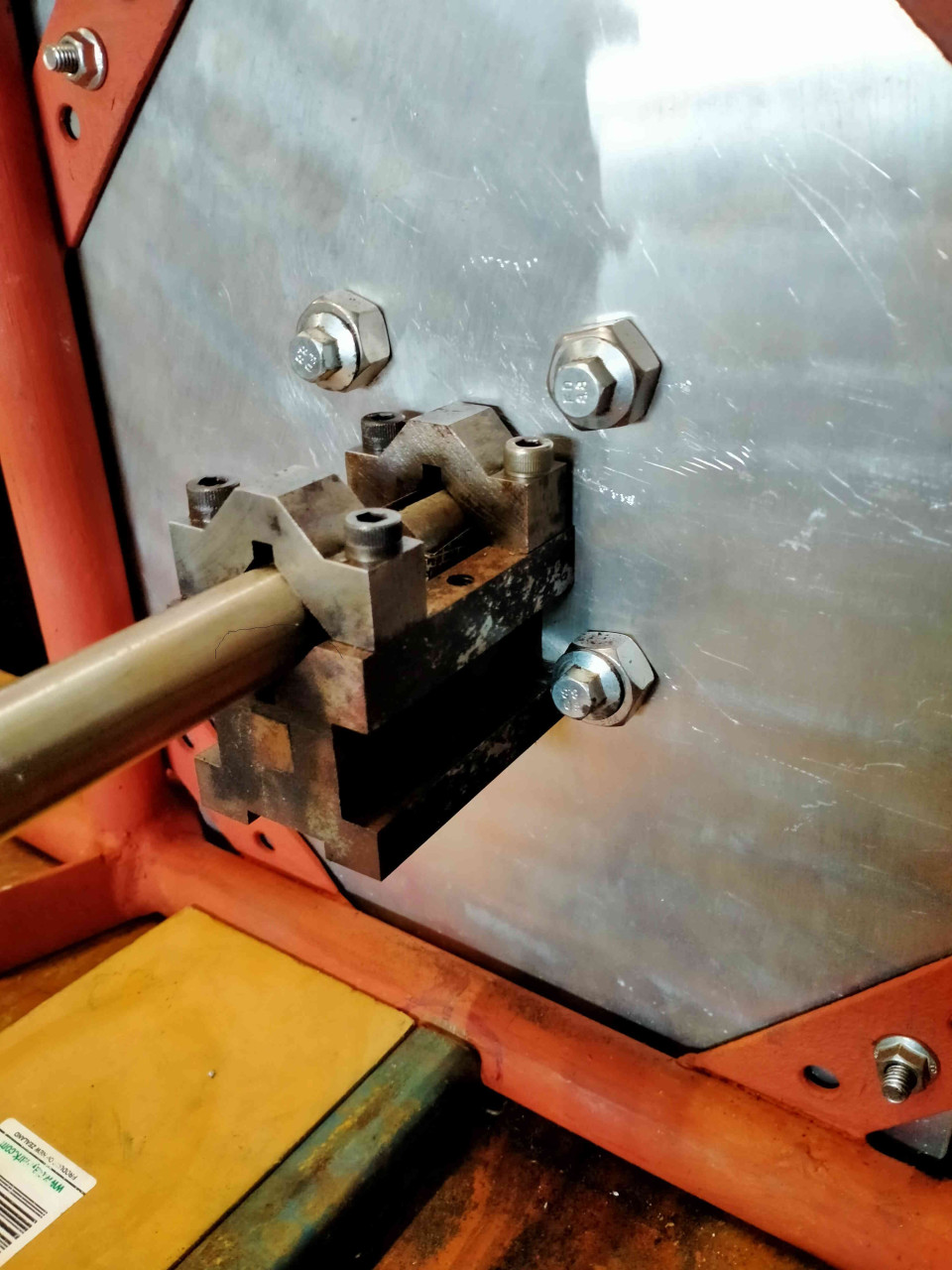
Pete_R reacted to this post about 2 months agoCut some key-ways in a shaft.
5mm slots in a 3/4" 304 SS. round bar.
First time I've done one like this, rather pleased with how they turned out.
The mounting fixture might have been a tech school project, I found it at a garage sale.
It's bolted down to the cross slide vice on my little lathe drill mill.
Budget Chinese slot drill in the drill...Cut some key-ways in a shaft.More
5mm slots in a 3/4" 304 SS. round bar.
First time I've done one like this, rather pleased with how they turned out.
The mounting fixture might have been a tech school project, I found it at a garage sale.
It's bolted down to the cross slide vice on my little lathe drill mill.
Budget Chinese slot drill in the drill chuck, 'cos my collet chuck has imperial sizes (1/4" collets, not 6mm).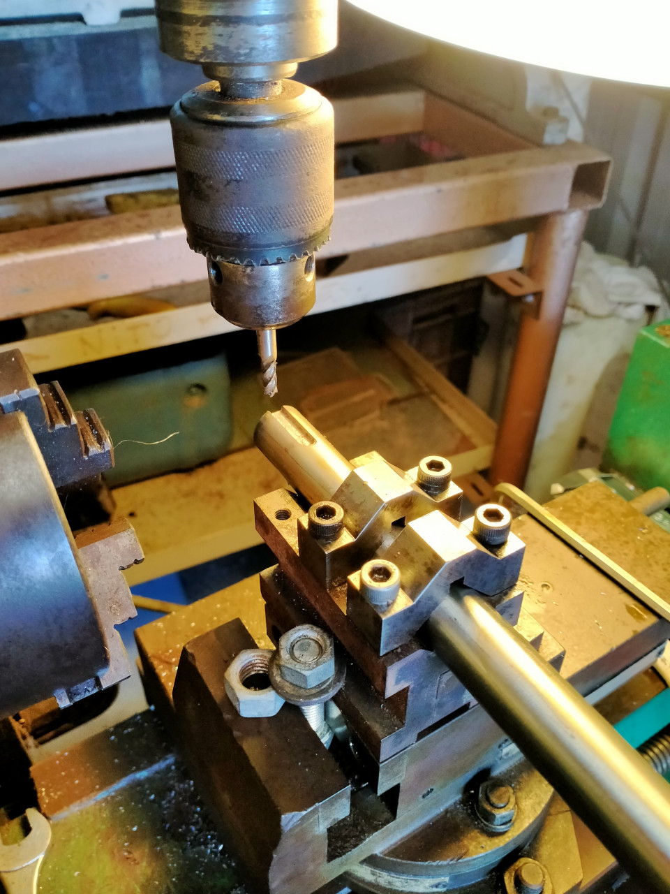 Post is under moderationStream item published successfully. Item will now be visible on your stream.
 -
Kingshill reacted to this post about 2 months agoHaven't updated in a while, but work is progressing slowly.
I've just about amassed all the parts I need to complete the build apart from brake lines and a chain.
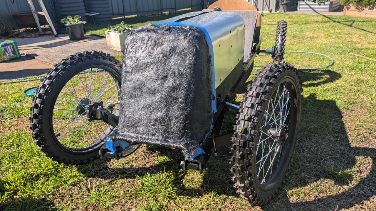
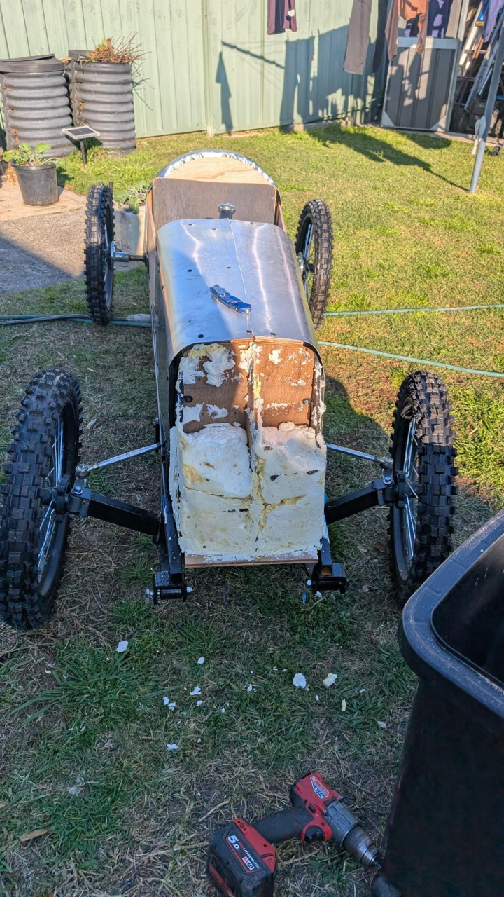
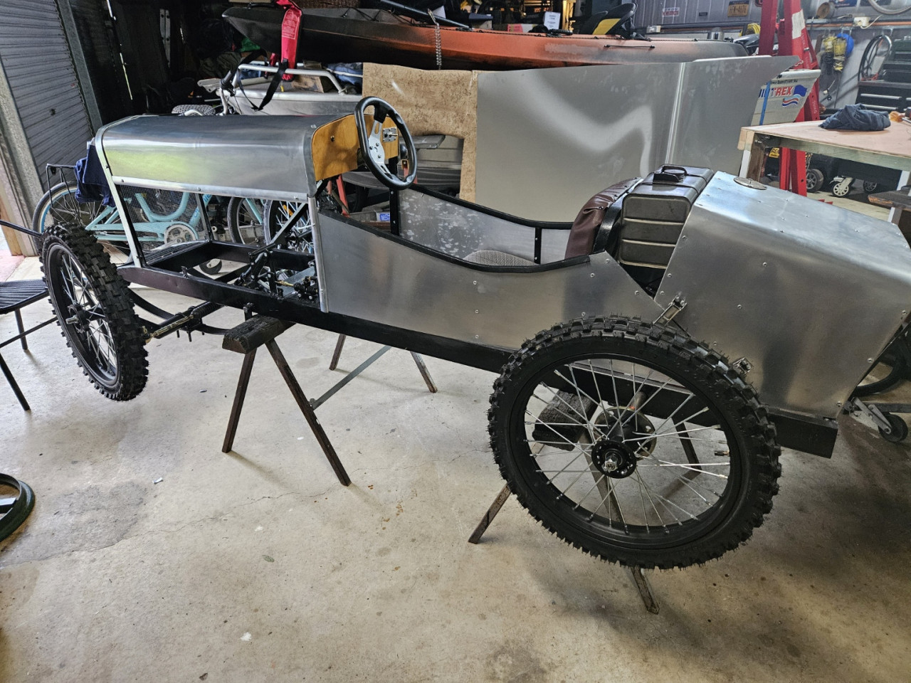
I now have a boxed in cabin which I am skinning in 0.5mm aluminium. I've found that with such a thin metal its quite easy to get a nice radius on body panels by running the sheet...Haven't updated in a while, but work is progressing slowly.More
I've just about amassed all the parts I need to complete the build apart from brake lines and a chain.
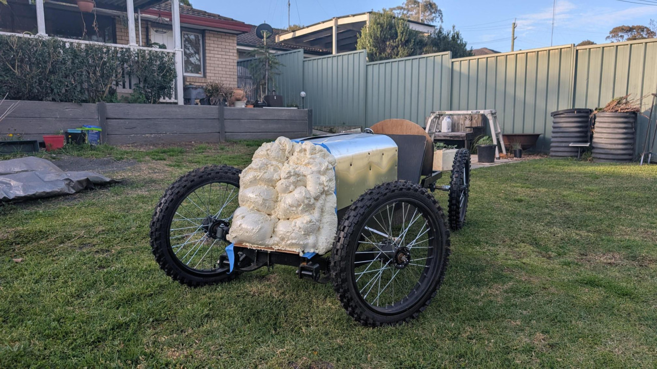
I now have a boxed in cabin which I am skinning in 0.5mm aluminium. I've found that with such a thin metal its quite easy to get a nice radius on body panels by running the sheet over your legs back and forth like you are drying yourself with a towel. Sounds crazy but it works.
Also made a foam buck for a nosecone. Got it into shape over the weekend and laid down my first layers of glass and resin. By far the messiest thing I have ever done. I just used chopped mat for the fibreglass, but in hindsight i would use woven cloth for straight lines and simple curves whilst saving the chopped mat for the more intricate compound curves. Now time to sand, cut and recoat where necessary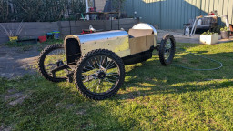
 Post is under moderationStream item published successfully. Item will now be visible on your stream.
 -
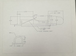
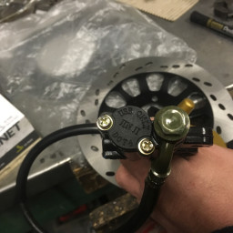
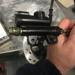
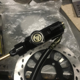
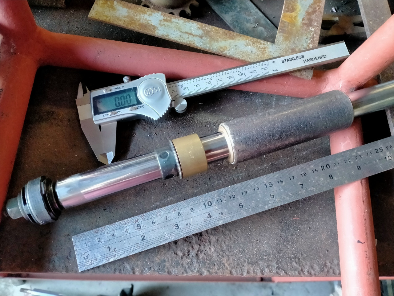
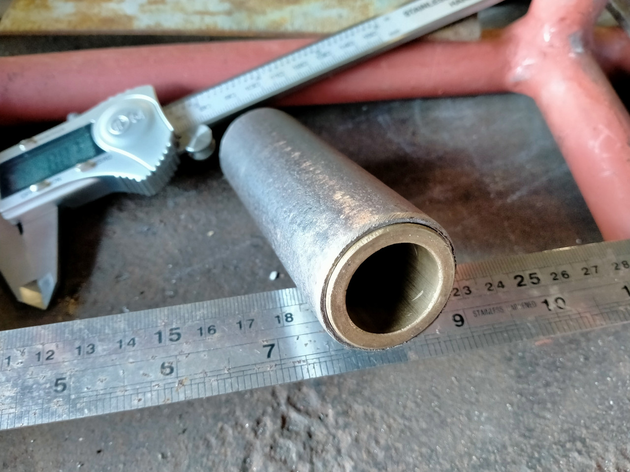
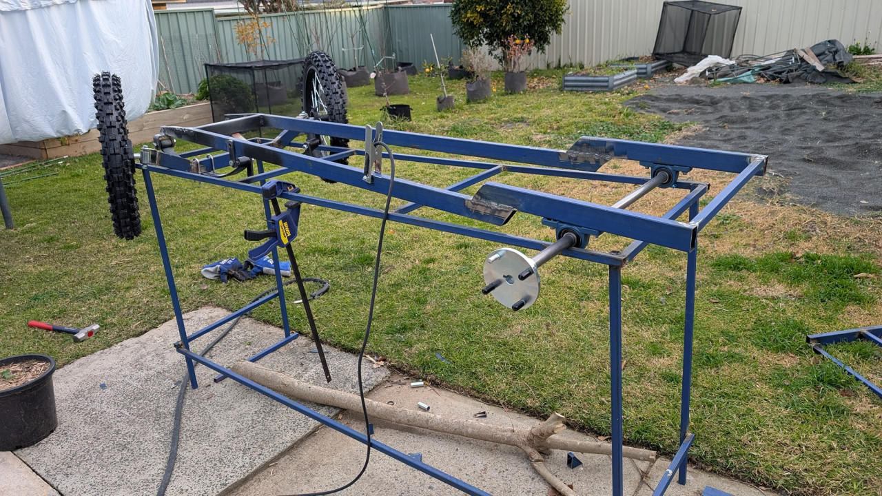
Pursang's "Vintage Morgan" Inspired 3 Wheeler. commented on this post about 3 months agoBrass bushes fitted into the sliding tube parts of the stub axles. Bored with my little lathe.
Pillars cut to length. One of those things that just accidentally worked out well,
the cut off point required the friction disc up against the welded on travel limiter.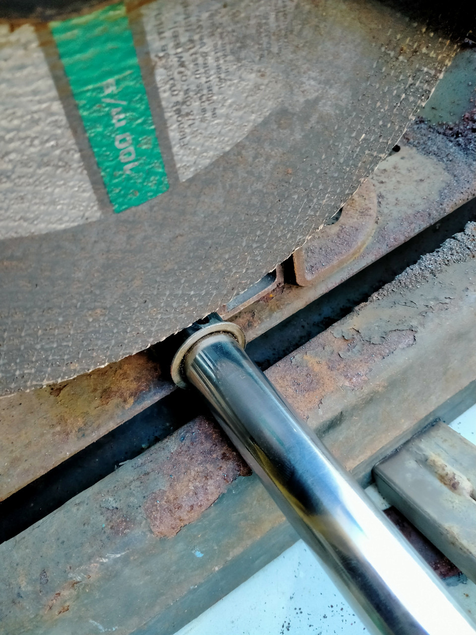
 Comments (3)
-
Nicely done
-
 Thanks Mick. Now, in an example of reality & honesty seldom seen on the internet (where everything seems perfect), I have a confession to make:
After More ... -
Moral of this story: Cut Once.....Kick yourself in the butt 3 times!
Post is under moderationStream item published successfully. Item will now be visible on your stream. -
-
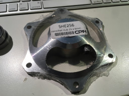
Pete_R commented on this post about 3 months agoThese might be interesting to some builders. 19mm x 35 X 11 bearings.
Because I'm building my own stub axles these bearings will allow me to fab them with HD 19mm axles.
So long as they are not made out of Chinese cheese they will be great.
Of course, at less than $2 ea. they could be replaced after each meeting!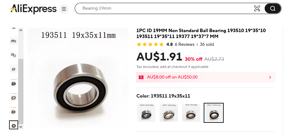 Comments (1)
-
I did similar with 17mm ID bearings. But at that price you would be crazy not to try them! Let us know how they turn out
Post is under moderationStream item published successfully. Item will now be visible on your stream. -
-
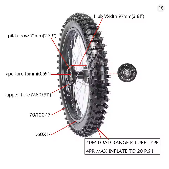
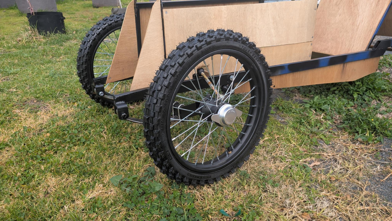
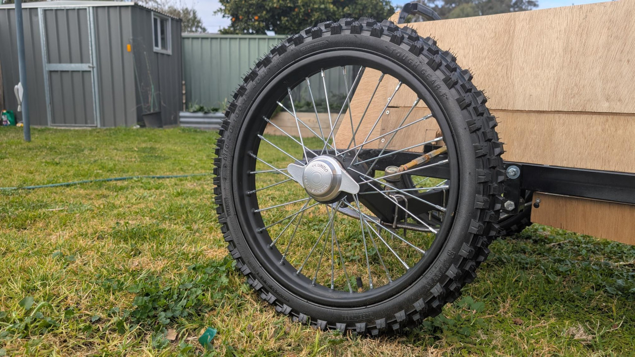
CKAlexander commented on this post about 1 month agoMy front wheels have arrived. Chinese dirt bike, nice quality.....and the price... around $54 ea. with free shipping. Whoo Hooo!
These were on Aliexpress, you need to spend a fair bit of time sussing out the bargains and pay particular attention to the shipping cost.
Bit of tension while monitoring the tracking, they were held up at Chinese...My front wheels have arrived. Chinese dirt bike, nice quality.....and the price... around $54 ea. with free shipping. Whoo Hooo!More
These were on Aliexpress, you need to spend a fair bit of time sussing out the bargains and pay particular attention to the shipping cost.
Bit of tension while monitoring the tracking, they were held up at Chinese airport for a couple of weeks to get on special "oversize'" freight flights.
I actually got some discount vouchers because of the delays.
My original plan was to build my own wheels around some nice 1970's Yamaha MX hubs I have. Then sourcing the 17" rims and custom spokes, tyres, tubes and rim bands, add the time to assemble and true and we are looking at hundreds & hundreds of $$$$$ for 2 wheels.
Now that I have the wheels, I can finish the pillar spacing and the stub axle design to meet the track width spec.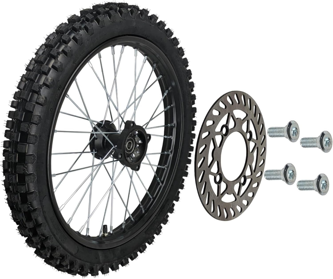
 Comments (5)
-
That's really reasonable, especially with the free shipping.
-
Nice. New parts day is the best day of the week
-
 Hi, can you please post the aliexpress ad? Thanks
 -
CKAlexander The ads and deals change almost daily. Takes patience and constant attention to find absolute bargains.
Here is a cheap 17" pitbike More ... -
Pursang Great thanks.
Post is under moderationStream item published successfully. Item will now be visible on your stream. -
-
Stream item published successfully. Item will now be visible on your stream.
-
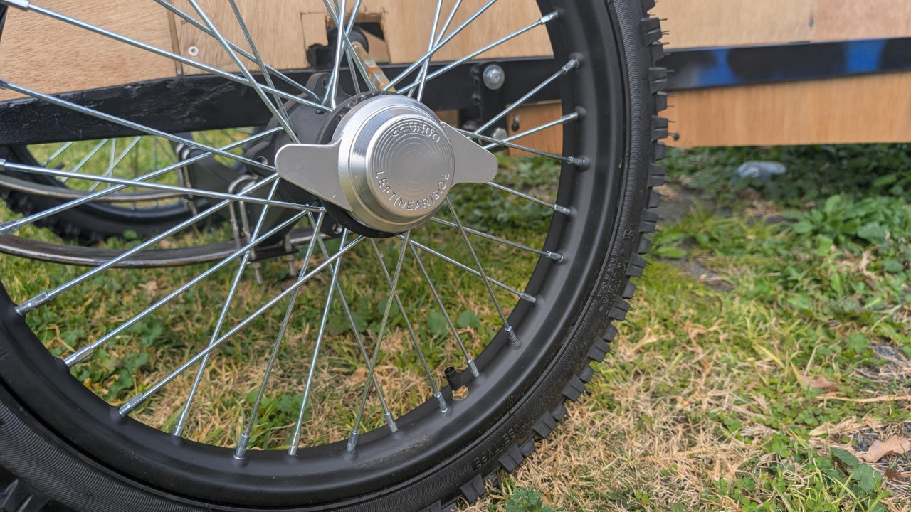
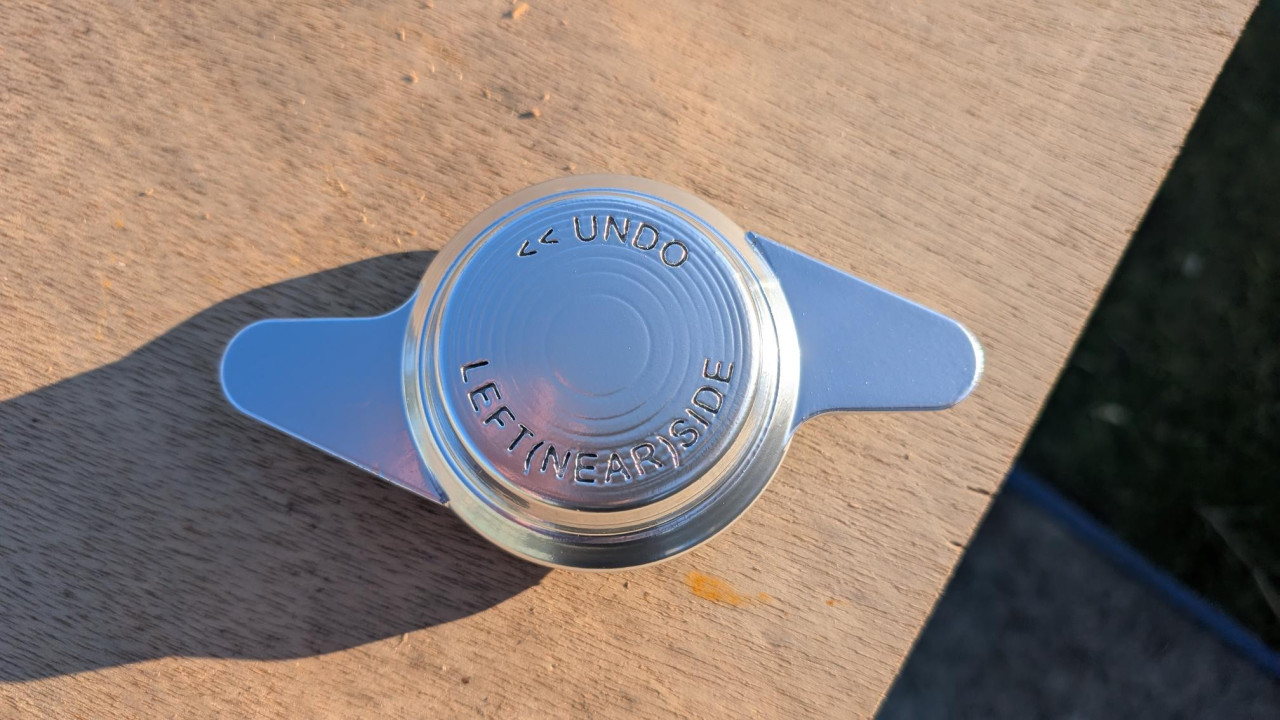
Pursang reacted to this post about 3 months agoHave 3D printed some hub caps for the cheap chinesium pit bike wheels. Also some weatherproofing in the guise of black paint, as I don't currently have shed, Still moving forward, albeit slowly.
 Comments (2)
-
 Amazing work! Can we buy some off you?
 -
Not at this very moment, but watch this space. Something maybe coming soon
Post is under moderationStream item published successfully. Item will now be visible on your stream. -
-
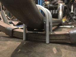
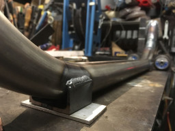
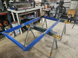
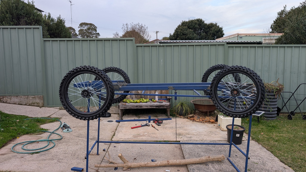
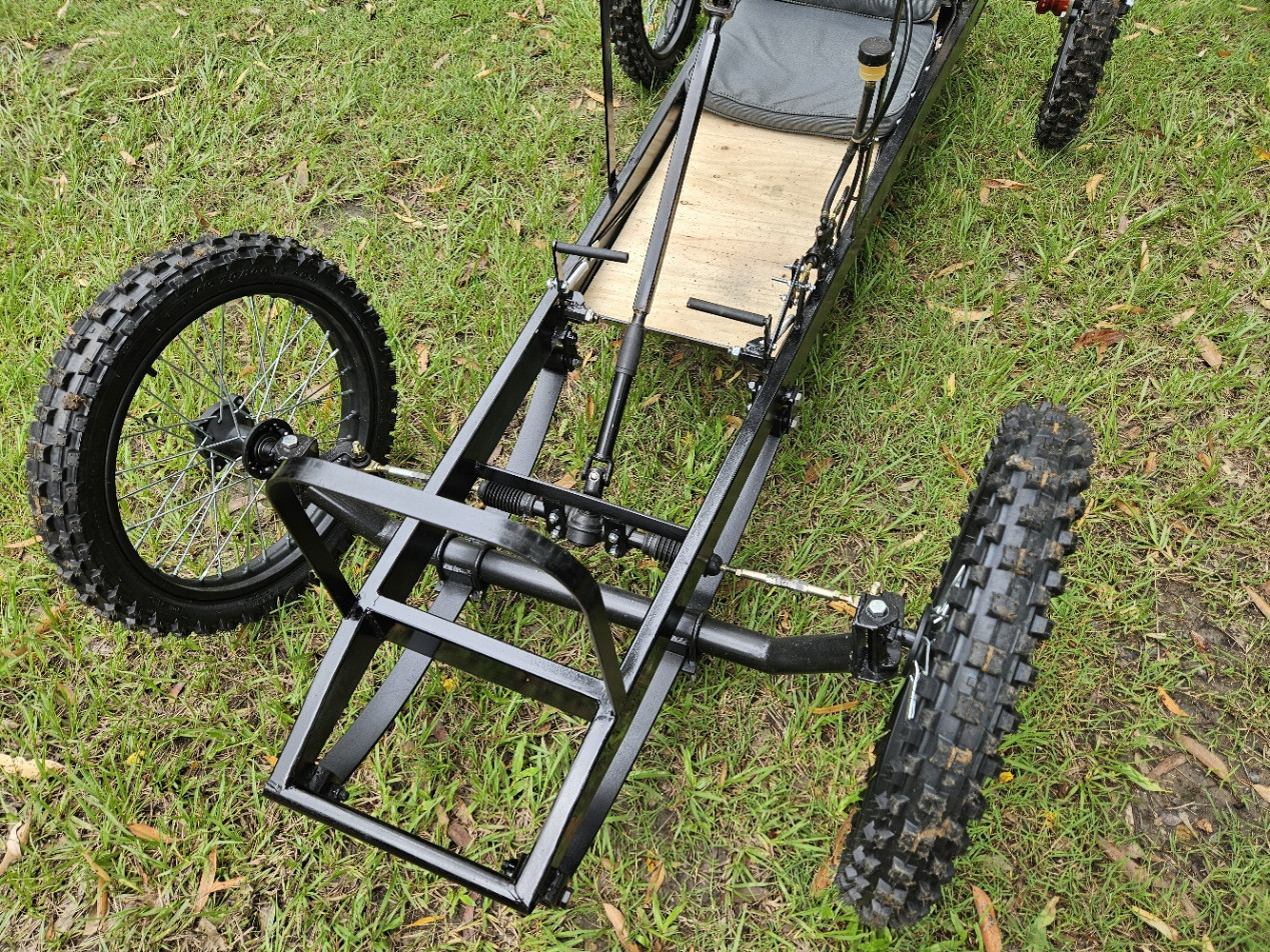
Pete_R reacted to this post about 4 months agoLots going on behind the scenes, but here is some visual evidence of progress. Front sub-frame assembly welded.
 Post is under moderationStream item published successfully. Item will now be visible on your stream.
 -
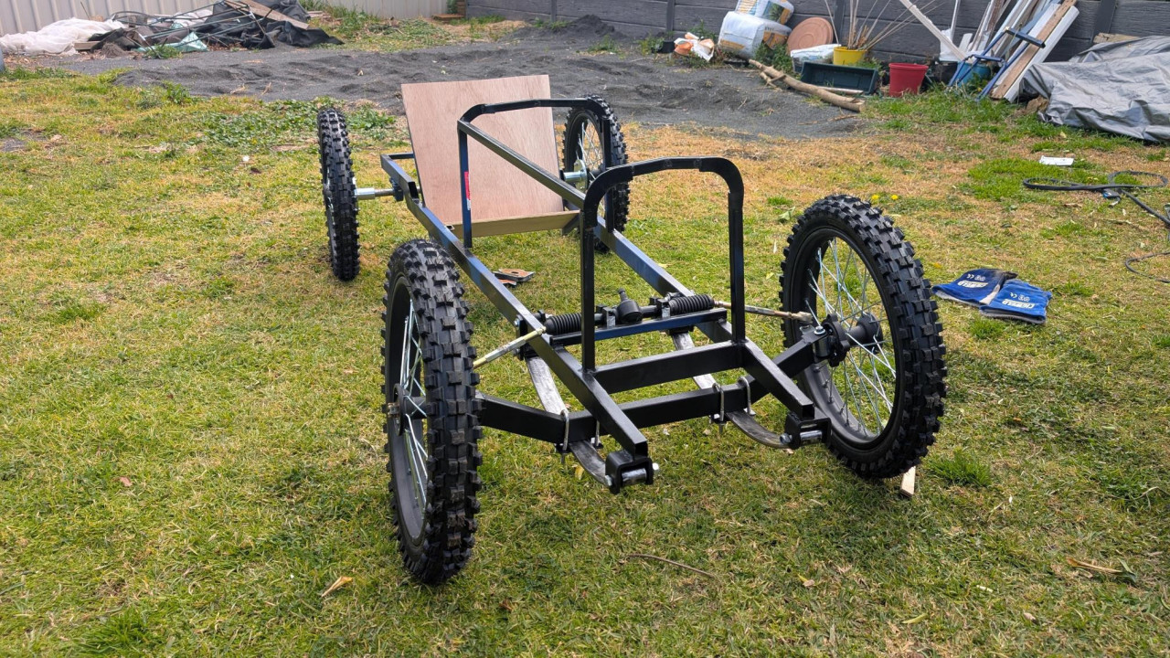
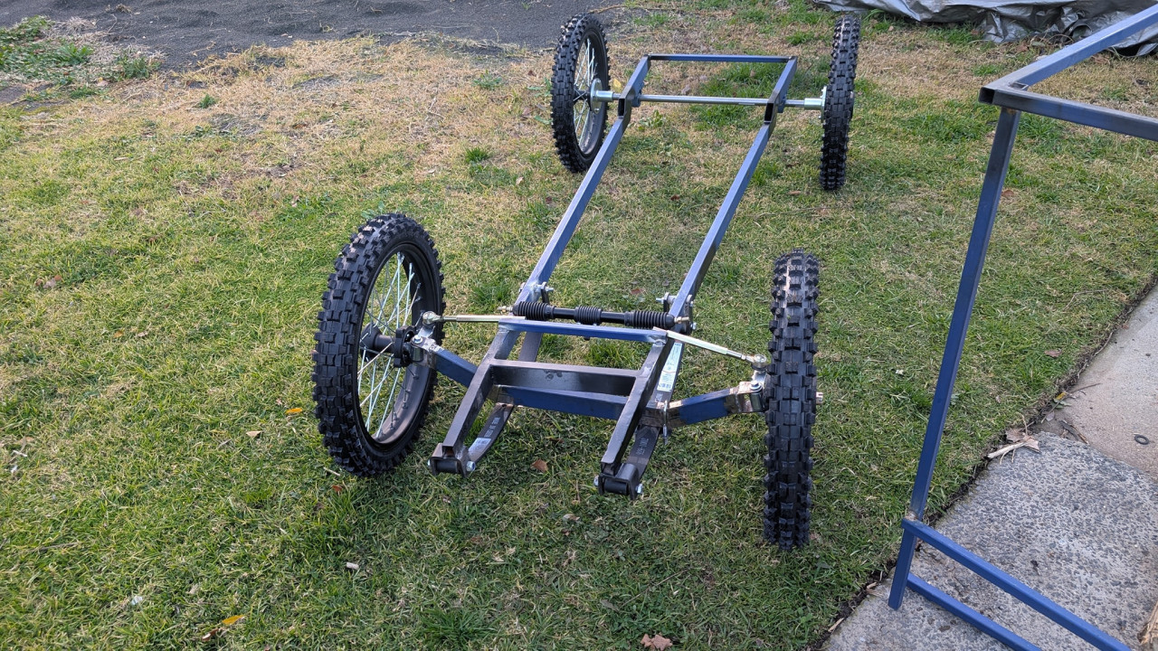
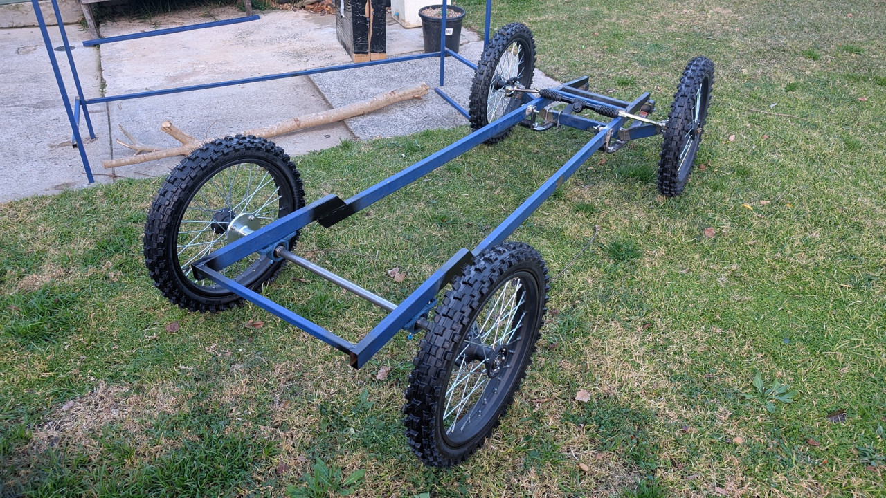
Pursang reacted to this post about 3 months agoA bit more progress, starting to shape a basic frame and and now have the rack and pinion steering complete
 Post is under moderationStream item published successfully. Item will now be visible on your stream.
 -
 Post is under moderationStream item published successfully. Item will now be visible on your stream.
 -
Post is under moderationStream item published successfully. Item will now be visible on your stream.
-
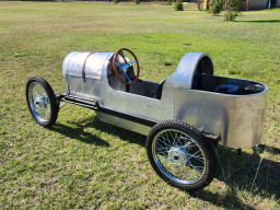
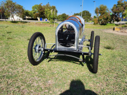
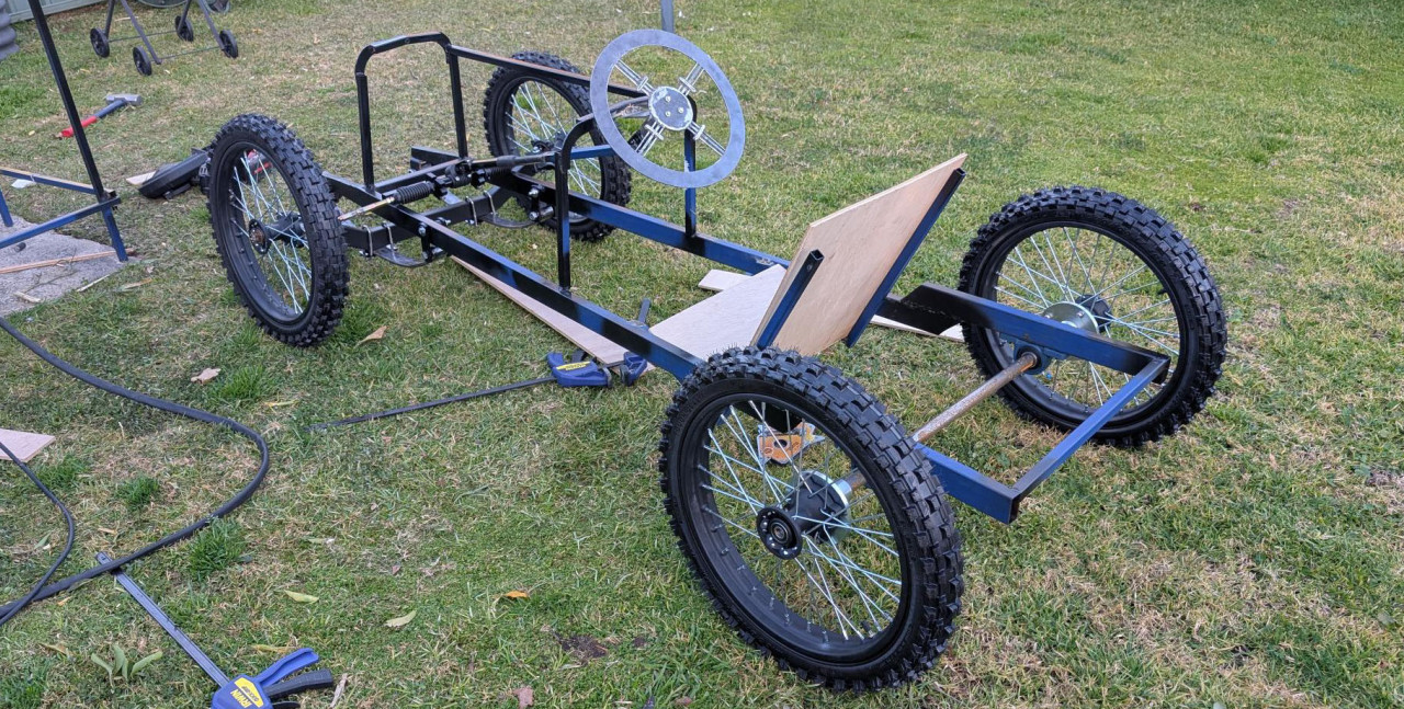
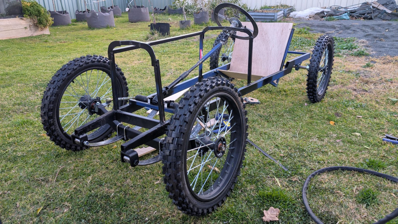
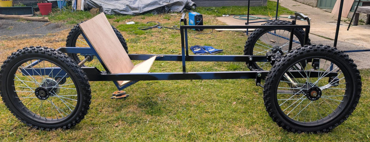
Pursang reacted to this post about 3 months agoMoving along slowly. It now rolls. Done a mock up with the wheels on to get an idea how it looks
 Post is under moderationStream item published successfully. Item will now be visible on your stream.
 -
 Post is under moderationStream item published successfully. Item will now be visible on your stream.
 -
Follow our Facebook page and connect with other Cyclekartistes
-
Post is under moderationStream item published successfully. Item will now be visible on your stream.
-
Post is under moderationStream item published successfully. Item will now be visible on your stream.
-
 Post is under moderationStream item published successfully. Item will now be visible on your stream.
 -
Post is under moderationStream item published successfully. Item will now be visible on your stream.
-
Stream item published successfully. Item will now be visible on your stream.
-
Stream item published successfully. Item will now be visible on your stream.
-
Post is under moderationStream item published successfully. Item will now be visible on your stream.
-
Post is under moderationStream item published successfully. Item will now be visible on your stream.
-
Stream item published successfully. Item will now be visible on your stream.


There are no activities here yet