
The next step on the bodywork journey is making the cowling. This is an important structural section as it provides support for the bonnet sides and starts to set the shape of the passenger compartment. Whist it does not structurally support the steering wheel in this car, it may provide support for the dashboard, depending on how I decide to mount it.
On the original cars the dashboard follows the cockpit and blends in to the trim that follows the cockpit around to the rear. It is very well executed and something that I would love to replicate, but may not be easy to do.

I suspect that I will end up blending the bottom corners of the dash into the cockpit but will try to follow the shape if I can.
The cockpit itself has a distinct opening shape that is angled to the bottom of the dash and then sweeps back and down towards the rear. This angular opening is another one of the characteristics I am keen to replicate.
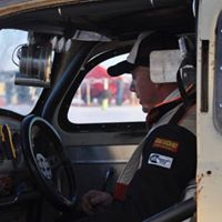
The other characteristic is that the cowl is relatively long. Most cars of the era have a long bonnet and a short cowl, but the Bentleys had a long cowl and a long bonnet. This proportion of bonnet to cowl is another thing to try and capture.

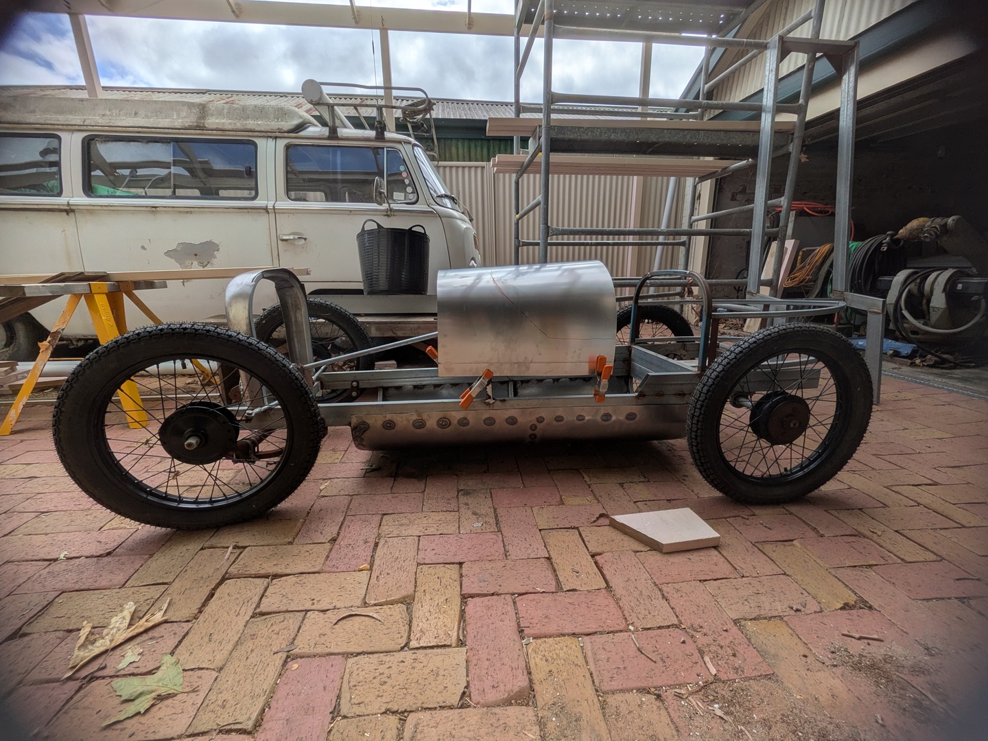
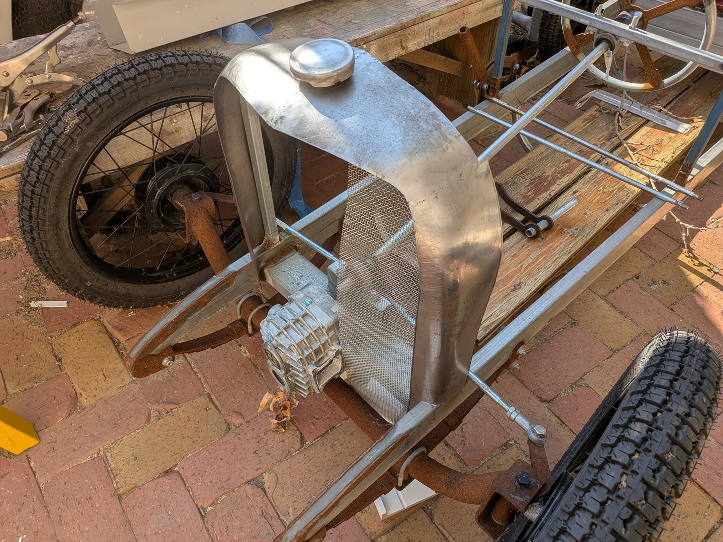
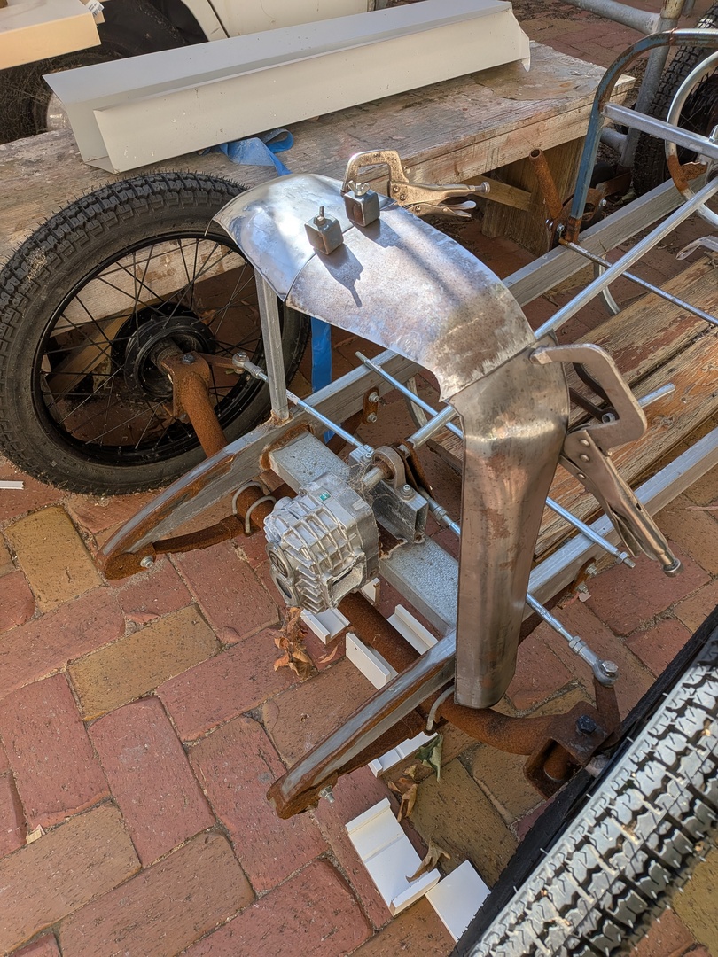
So I decided that the best way to make the cowl was to simply fold a sheet over the A-pillar hoop - setting the front of it in approximately the right position, and then eventually cutting the cockpit shape at the rear.
But the problem that I found was that the blanks I had cut were too small to reach all the way to meet the rocker. Stopping some 100mm short.

This is an issue of my own doing. I purchased a full sheet and then had it cut into 1200 x 600mm pieces so that I could fit it in the car, thinking that they would be ample. But I guess that's just not my luck lol. So I need to go back to the drawing board with how I make the cowl.
One option would be to make it in two halves and weld them together right in the middle. This may actually be of benefit as it would be easier to put some shape into the cowl where it flicks up at the cockpit opening.
The other option is to weld on the extra 100mm of material and then shape as one panel. This has the advantage that the front edge can then be rolled in one continuous profile, rather than attempting to weld it, which I suspect will be a PITA.
So no easy choice and no clear winner. Maybe options 3 is go buy more ali, but I'd rather not and it's got to be welded anyhows so in for a penny - in for a pound.
And that's as far as I have got with the cowl so far. Two steps forwards and one step backwards. I'm beginning the realise, that's just how I roll. :D


.jpg")


